Electric power steering system

Inactive Publication Date: 2008-06-26
NSK LTD
View PDF5 Cites 24 Cited by
  • Summary
  • Abstract
  • Description
  • Claims
  • Application Information

AI Technical Summary

Benefits of technology

[0020]The invention has been made in view of the situations and an object thereof is to provide an electric power steering system which can reduce vibration and noise generated when the steering is held while securing the operating performance when the steering wheel is operated

Problems solved by technology

Namely, in recently developed electric power steering systems, although the capacity is increased, since the AD converter which is used in the control unit which is configured mainly by a CPU continues to have a resolution performance of 10 bits in order to prevent an increase in the production costs, the resolution performance becomes relatively rough under the circumstances in which a large current tends to be used.
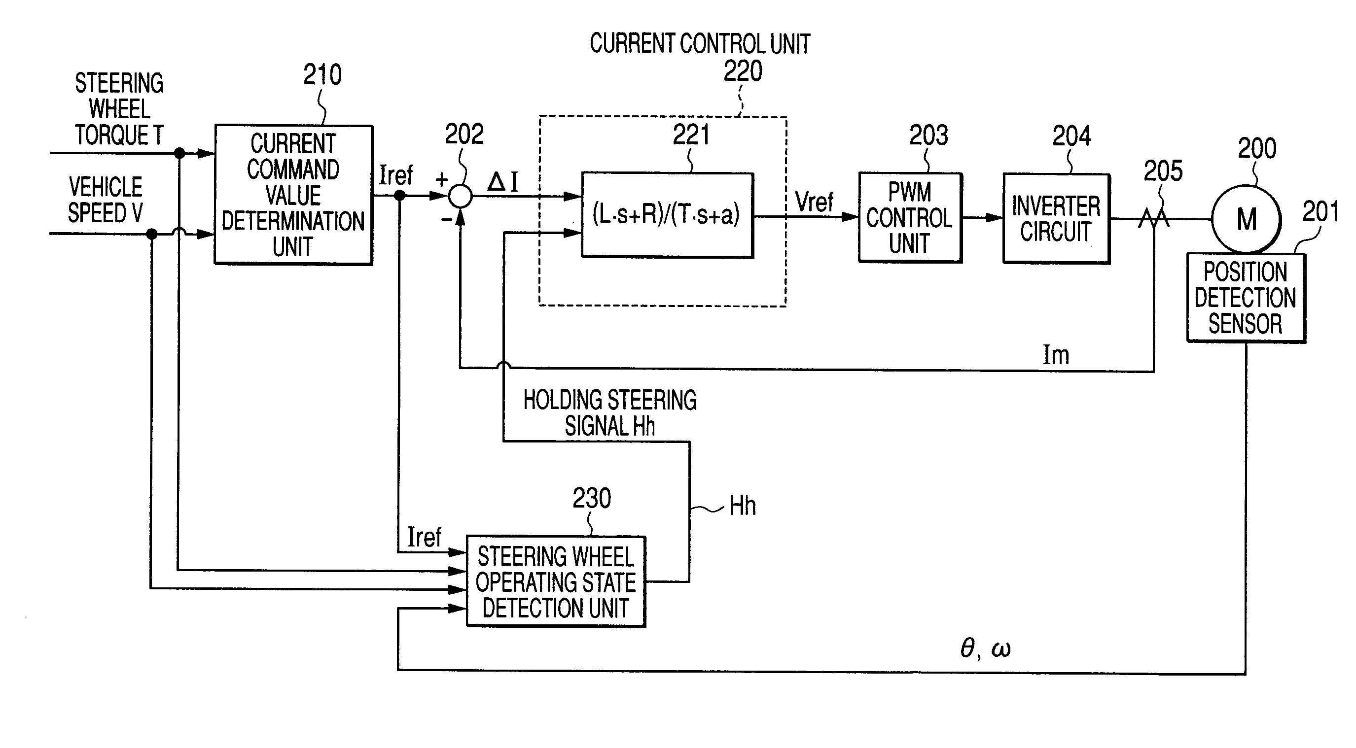
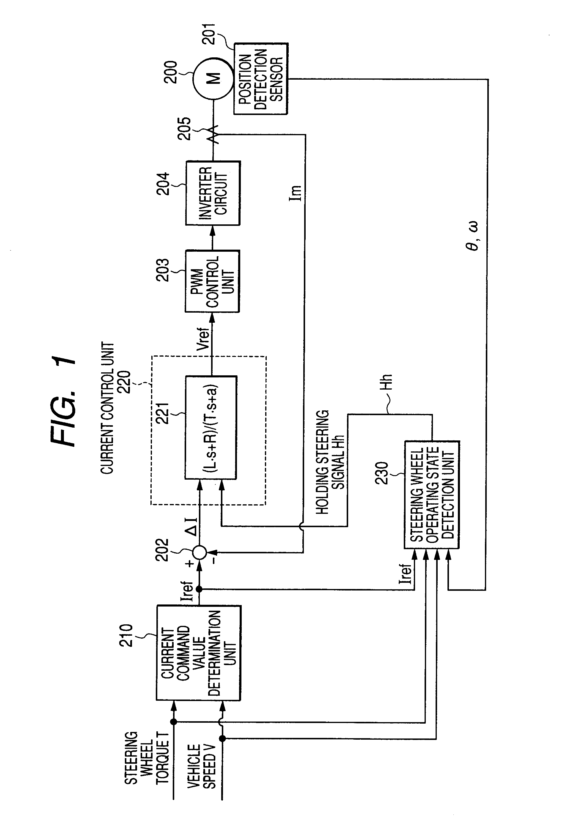
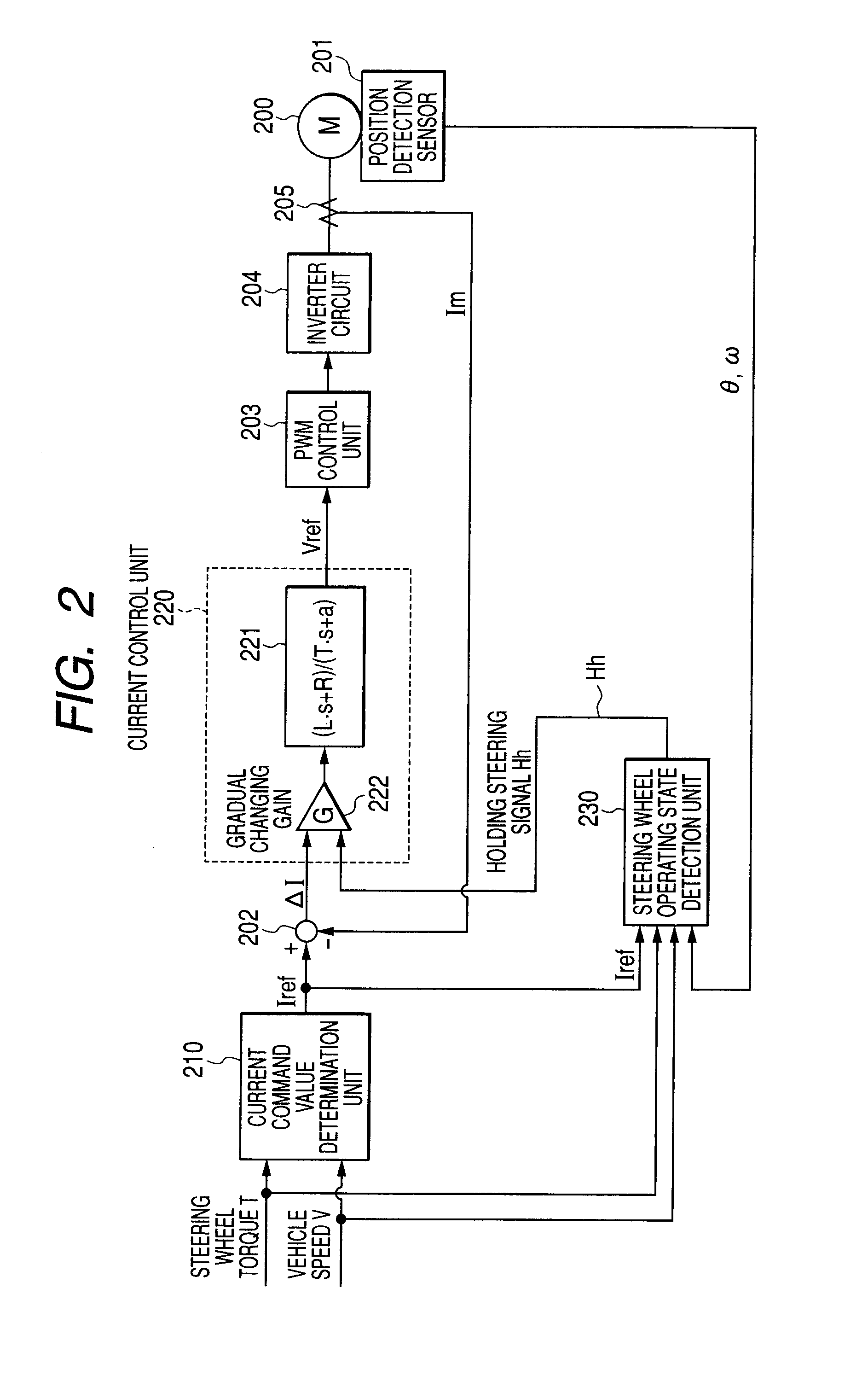
In addition, an error such as noise that is produced by the roughness of the resolution performance is amplified by a feedback gain in which the gain becomes infinity which results when the deviation ΔI is small which results, in turn, in the holding steering state or when the steering wheel is rotated slowly, and the operation error so amplified causes the vibration and noise of the steering wheel, resulting in a problem of causing the driver to feel an uncomfortable sensation.
However, in a current control including an integral term, since its gain becomes infinity in a steady state, in the holding steering state or when the steering wheel is rotated slowly, which is the steady state of an electric power steering system, the driver feels vibration and/or noise via the steering wheel, and this results in a problem that the driver feels the sensation of uncomfortableness when the driver operates the steering wheel.
With the electric power steering system described in JP-A-2000-108916, it is difficult to make a design to determine the adjusting gain which varies according to a deviation in current feedback, and since the gain of the integral term is infinity, even in the event that the adjusting gain is made as small as possible, the total gain becomes large.
Hence, the problem still re

Method used


Image

  • Electric power steering system
  • Electric power steering system
  • Electric power steering system

Examples


first embodiment

[0107]In this way, in a first embodiment of the invention, only when the response control unit operates at the same time that the rack end protecting function operates, the recovery time of the response of the current control when reset from the judgment of the steering holding is made shorter than normal, whereas if the rack end protecting function is not in operation, the recovery time of the response of the current control is made to remain as when normal.

[0108]FIG. 8 shows how it works. When the steering wheel operating state is judged to be switched from the steering state to the holding steering state, the response is made to ramp down over a period of time T1, and when the protecting function operating condition is met while it is judged the steering wheel is in the holding steering state, the response is made to ramp down as is indicated by a solid line for a short period of time T2 for judgment of the steering wheel operating state, whereas if the protecting function operat...

second embodiment

[0109]In addition, FIG. 9 shows a second embodiment of the invention, in which a rack end judgment unit 240 as a rack end protecting function is provided, so that when judging that the vicinity of the end of a rack is reached, the rack end judgment unit 240 outputs a rack end signal Re so as to be inputted into a steering wheel operating state judgment unit 230, whereby a current command value Iref from a current command value determination unit 210 is limited, and a current (Im) that is to be supplied to a motor 200 is limited. In addition, in the event that the rack end signal Re is inputted into the steering wheel operating state judgment unit 230 and the rack end signal Re is judged, a response control function is switched off, and the steering holding signal Hh is made not to be outputted from the steering wheel operating state detection unit 230.

[0110]An operation example of the control system that is configured as has been described above will be described by reference to a f...

third embodiment

[0116]Third embodiment of the invention shown in FIG. 11 illustrating a configuration example in which the overheat protection and the response control are performed while associating it with the configuration example shown in FIG. 6, and an overheat detection unit 250 is provided for detecting overheat based on a motor current Im and a temperature sensor 251. When the overheat detection unit 250 detects overheat of the motor and / or the whole control system, the overheat detection unit 250 outputs an overheat signal Hd. Then, as with the rack end signal Re, the overheat signal Hd is inputted a current command value determination unit 210 and an inverter circuit 204 so as to limit the current, and the same signal is also inputted into a switching control unit 241. As this occurs, for example, in the current command value determination unit 210, the output is limited according to the time that has elapsed. For example, a gain module which decreases its gain from a 100% gain to a 50% g...


PUM


Abstract

There is provided an electric power steering system including a motor for imparting a steering assist force to a steering system of a vehicle, a current command value determination unit which determines a current command value based on a steering torque and a vehicle speed, a motor angular velocity detection unit which detects or estimates an angular velocity of the motor, and a drive control unit which controls the motor based on the current command value so determined, the electric power steering system including a protecting function unit which prevents the overheat of the motor or the whole of a control system and a response control unit which decreases the response of a current control when it is judged a holding steering state.

Description

TECHNICAL FIELD[0001]The present invention relates to an electric power steering system and more particularly to an electric power steering system which has improved the steering feeling when the protecting function such as the rack end protecting function is in operation and when the response control function is in operation.RELATED ART[0002]An electric power steering system for imparting an assist force (a steering assist force) to a steering system of a vehicle by virtue of the rotational force of a motor is configured such that the rotational force of the motor is imparted to a steering shaft or a rack shaft as a steering assist force by a transmission mechanism such as gear wheels or a belt via a reduction mechanism. The configuration of an electric power steering system like this will be described by reference to FIG. 13.[0003]In the electric power steering system described above, a column shaft 2 of a steering wheel 1 is coupled to tie rods 6 of steered wheels by way of a red...

Claims


Application Information

Patent Timeline
IPC IPC(8): B62D6/00B62D5/04
CPCB62D5/0469B62D5/0496B62D5/0481B62D5/04B62D6/00
Inventor YAMAMOTO, SATOSHI
Owner NSK LTD
Why Eureka
Try Eureka