
System for the Disinfection of Low-Conductivity Liquids

Inactive Publication Date: 2008-07-03
CONDIAS
View PDF17 Cites 17 Cited by
  • Summary
  • Abstract
  • Description
  • Claims
  • Application Information

AI Technical Summary

Benefits of technology

[0012]With small electrochemical cells with a throughput of less than 1000 l / h, a reliable sterilization requires a considerable expenditure in terms of machinery. The disinfection unit according to the invention can be embodied as an independent system in which the liquid and the oxidizing agent are intermixed and an improved sterilization thus occurs. This applies in particular to the use of electrochemical cells with electrodes between which a polymer solid-state electrolyte in membrane technology is arranged. The use of electrode arrangements renders possible the disinfection of rainwater, the disinfection of ultra-pure water circuits in the semiconductor industry and pharmaceutical industry or with the removal of organic contamination in rinsing waters, with the purification of water for the food industry and cosmetics industry, which arrangements prevent the algae or bacteria growth through the oxidizing agents produced or, with high contaminations, achieve a degradation. The germs are oxidized by the oxidizing agents and thus killed or inactivated. It is also possible to purify a germ-contaminated system by retrofitting a disinfection unit.
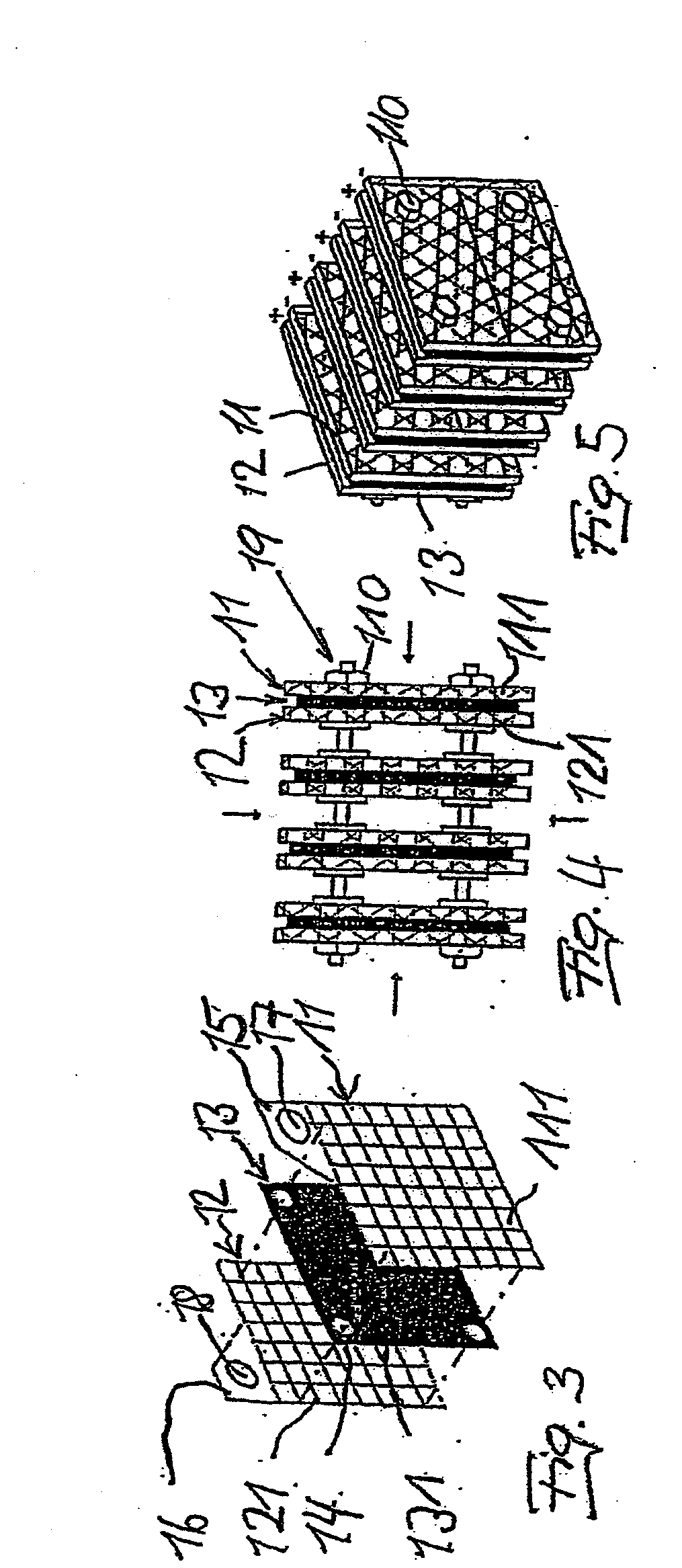
[0030]The electrode arrangement according to the invention also makes it possible in a surprisingly simple manner to move away from the flat electrodes hitherto customary. It is thus possible, e.g., to embody two electrodes in a rod-shaped manner and to realize the polymer solid-state electrolyte between the electrodes in that the solid-state electrolyte alternately wraps around the electrodes in the form of a strip under preload. The strip can thereby be mounted wrapping around each of the two electrodes in the form of a figure eight, whereby the wrapping occurs with a certain preload in order to ensure the intimate contact. The two electrodes can be pressed against the strip sections of the polymer solid-state electrolyte located between the electrodes, e.g., by a wire-shaped material wrapped around the electrodes, with the ends twisted together to generate the pressure. The wire-shaped material can thereby preferably be an insulating material or bear against the electrodes via an insulating layer.

Problems solved by technology

With small electrochemical cells with a throughput of less than 1000 l / h, a reliable sterilization requires a considerable expenditure in terms of machinery.

Method used


Image

  • System for the Disinfection of Low-Conductivity Liquids
  • System for the Disinfection of Low-Conductivity Liquids
  • System for the Disinfection of Low-Conductivity Liquids

Examples


Embodiment Construction

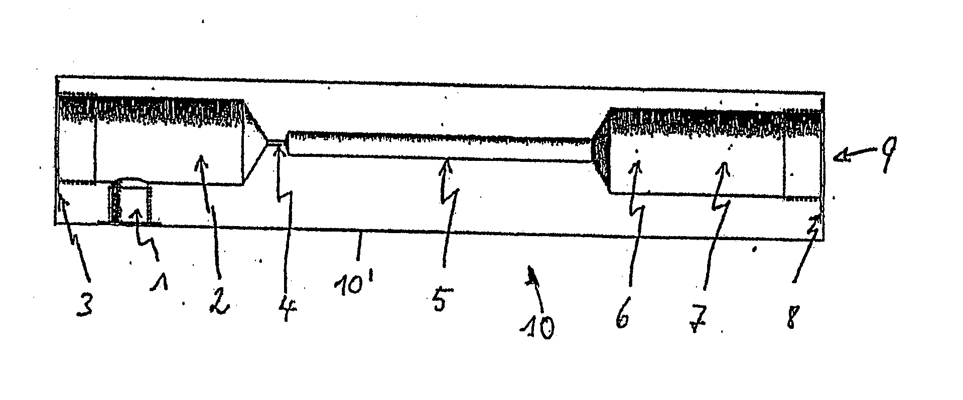
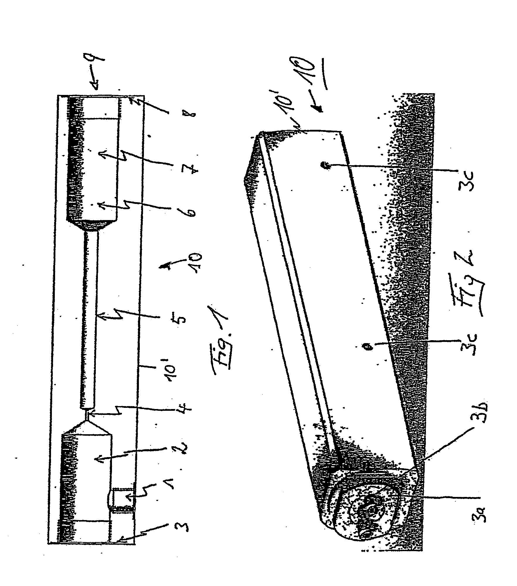
[0047]FIG. 1 shows a basic system setup of a disinfection unit 10 with an inlet 1 through which the liquid to be disinfected, preferably water, is guided into an electrode-accommodating chamber 2. On the front face, the electrode-accommodating chamber 2 has a gasket surface 3 to accommodate an electrode pad 3a, as shown in FIG. 2. FIG. 2 shows the disinfection unit 10 from the outside in an overall view. Sockets 3b for the electrical connection from outside are provided on one electrode pad 3a. Bores 3c are provided in the housing 10′ that is embodied in one piece, preferably manufactured of ozone-resistant plastic, for a fastening device of the total system 10 at the designated place of use.

[0048]The liquid flows around the electrodes within the electrode-accommodating chamber 2 embodied or arranged in the housing 10′, and an oxidizing agent, preferably ozone, is produced from the liquid. This ozone, together with the inserted liquid, is guided through a restrictor point 4 in the f...


PUM

PropertyMeasurementUnit
Lattice constantaaaaaaaaaa
Pressureaaaaaaaaaa
Electrical conductivityaaaaaaaaaa

Abstract

A system for the disinfecting of low-conductivity liquids, in particular water, is provided. The system includes an electrochemical cell in which electrodes are arranged such that the liquid flushes or flows around them, and in which oxidizing agents are produced from the liquid by applying a current. A mixing unit is mounted downstream of the electrochemical cell in the flow direction, in which mixing unit the oxidizing agents are intermixed with the liquid.

Description

CROSS-REFERENCE TO RELATED APPLICATIONS[0001]The present application claims priority under 35 U.S.C. §119 of German Patent Application No. 20 2005 003 720.6, filed on Mar. 4, 2005.BACKGROUND OF THE INVENTION[0002]1. Field of the Invention[0003]The invention relates to a system for the disinfection of low-conductivity liquids, in particular water, with an electrochemical cell in which electrodes are arranged such that the liquid flushes or flows around them, and in which oxidizing agents are produced from the liquid by applying a current.[0004]2. Discussion of Background Information[0005]There are diverse methods for the disinfection of small amounts of liquid, i.e., amounts of less than 1000 l / h. These methods are used in particular for drinking water purification, the production of ultra-pure water or the provision of process waters. Disinfecting can be carried out, e.g., by a metered addition of chemicals. These chemicals, however, have to be filtered out of the water flow after e...

Claims


Application Information

Patent Timeline
IPC IPC(8): C02F1/467
CPCA61L2/03C02F1/281C02F2201/46195C02F1/4672C02F2201/4613C02F1/32
Inventor FRYDA, MATTHIASMATTHEE, THORSTEN
Owner CONDIAS
Learn More