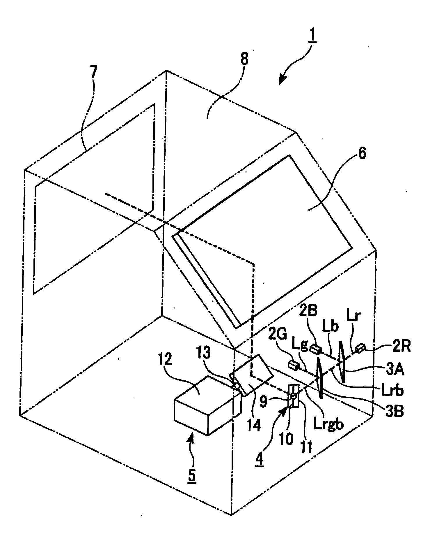
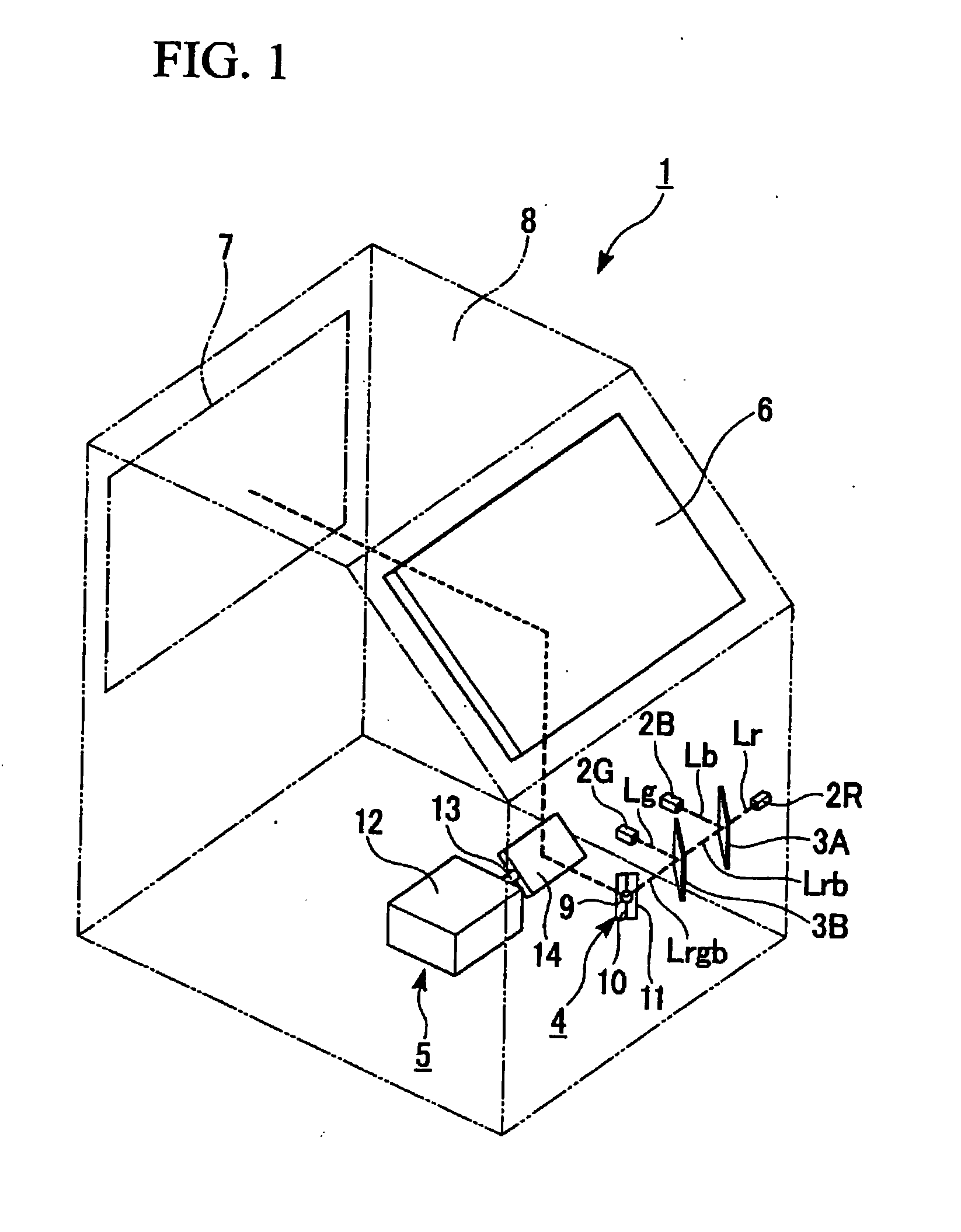
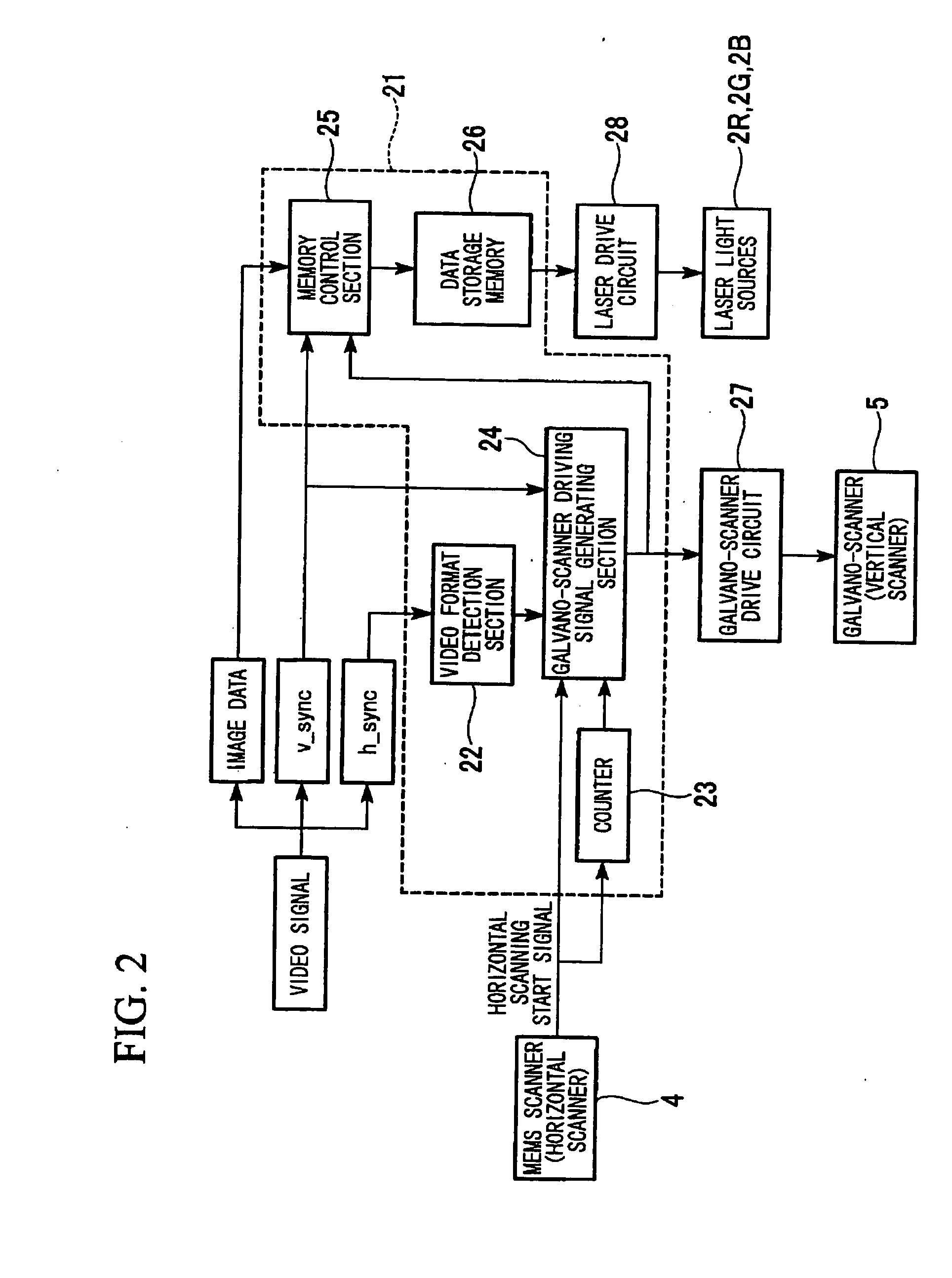
Scanning type image display device
a display device and scanning type technology, applied in the direction of instruments, color television details, optics, etc., can solve the problems of image distortion, inability to ensure sufficient scanning amplitude, complicated structure and control of the scanning system, etc., and achieve the effects of high speed, high accuracy, and small siz
- Summary
- Abstract
- Description
- Claims
- Application Information
AI Technical Summary
Benefits of technology
Problems solved by technology
Method used
Image
Examples
first embodiment
Modification of First Embodiment
[0149]The first embodiment described above covered the case of the operation speed of the MEMS scanner 4 being faster than the design value. Hereinafter, the opposite case of a slower MEMS scanner 4 shall be considered.
[0150]For example, in the case of a design target value of 33.75 kHz under the same preconditions as the embodiment described above, assume that a MEMS scanner 4 is produced that resonates at 32.5 kHz.
[0151]In this case, the MEMS scanner 4 with a resonance frequency of 32.5 kHz draws 1,083.33 lines (scannable line number) in 1 frame ( 1 / 60 second).
[0152]Even in this case, since nothing is drawn during the flyback time from line 1,081 to line 1,125, the picture is unaffected.
[0153]Therefore, similarly to the embodiment described above, during the time required for scanning of the 0.67 line portion until the 1,084th line after the horizontal scanning of 1,083.33 lines is complete, the galvano-scanner 5 is temporarily stopped to stop the v...
second embodiment
[0159]A second embodiment of the invention will be described herein
[0160]The basic constitution of the laser scan-type image display device of the second embodiment is completely identical to the first embodiment, with only the method of controlling the restart timing of the vertical scanning differing from the first embodiment.
[0161]This point will be described with reference to FIG. 4.
[0162]FIG. 4 is a timing chart of various types of control signals in the control section in the image display device of the second embodiment.
[0163]In the case of the second embodiment, as shown in FIG. 4, the horizontal scan line number (i.e., the number of horizontal scanning start signals) from the vertical scanning start signal of the first frame to the vertical scanning start signal of the second frame is 1,134 lines, and the horizontal scan line number from the vertical scanning start signal of the second frame to the vertical scanning start signal of the third frame is 1,133 lines.
[0164]That ...
third embodiment
[0171]A third embodiment of the invention will be described hereinafter.
[0172]The basic constitution of the laser scan-type image display device of the third embodiment is completely identical to the first embodiment, with the method of controlling the restart timing of the vertical scanning being the same as the second embodiment.
[0173]Also, the third embodiment differs from the second embodiment only on the point of considering fluctuations in the resonance frequency of the MEMS scanner.
[0174]FIG. 5 is a timing chart of various types of control signals in the control section in the image display device of the third embodiment.
[0175]In the third embodiment, under the same preconditions as the first embodiment, the MEMS scanner 4 can be many to meet the design target value, so that the resonance frequency thereof becomes exactly 33.75 kHz.
[0176]In this case, it would seem that no problems would arise even if driven continuously at 60 Hz without temporarily stopping the galvano-scann...
PUM
 Abstract
Description
Claims
Application Information
 - R&D
- Intellectual Property
- Life Sciences
- Materials
- Tech Scout
- Unparalleled Data Quality
- Higher Quality Content
- 60% Fewer Hallucinations
Browse by: Latest US Patents, China's latest patents, Technical Efficacy Thesaurus, Application Domain, Technology Topic, Popular Technical Reports.
© 2025 PatSnap. All rights reserved.Legal|Privacy policy|Modern Slavery Act Transparency Statement|Sitemap|About US| Contact US: help@patsnap.com


