Mask With Focus Measurement Pattern And Method For Measuring Focus Value In Exposure Process Using The Same

a technology of focus measurement and exposure process, which is applied in the field of microlithography, can solve the problems of deformation of pattern transfer onto the wafer, inability to reliably represent the degree of focus change, and considerable difficulty in accurate focus measurement, so as to achieve the effect of easy manufacturing of the mask

Active Publication Date: 2008-07-03
SK HYNIX INC
View PDF5 Cites 7 Cited by
  • Summary
  • Abstract
  • Description
  • Claims
  • Application Information

AI Technical Summary

Benefits of technology

[0023]According to the invention, since the line shortening phenomenon which is generated at the circuit patterns according to the focus change is used, it is possible to measure more directly the focus environment applied to the circuit patterns formed on the wafer. Also, the focus measurement patterns can be formed together in the process of patterning a layer deposited on the mask to form a mask pattern for the transfer of the circuit patterns. An additional process for forming the focus measurement patterns on the mask, e.g., a mask substrate etching, process for a phase reversal region, is not needed. Accordingly, since an additional process in manufacturing the mask is not added, the mask can be manufactured more easily.

Problems solved by technology

However, the practical focus value may change from the optimum focus value for the wafer regions, which causes a deformed pattern transfer onto the wafer when compared to the exposure performance at the optimum focus value.
If the uniformity of the etched pattern is relatively low, the extent of pattern shift on the wafer cannot reliably represent the degree of focus change.
However, because it is so difficult to uniformly perform the etching on the mask substrate, there is considerable difficulty in the accurate focus measurement.
Also, attack or damage may occur on the light-shielding pattern of chromium or the surface of the mask substrate in the etching process, and it causes quality degradation of the mask.

Method used


Image

  • Mask With Focus Measurement Pattern And Method For Measuring Focus Value In Exposure Process Using The Same
  • Mask With Focus Measurement Pattern And Method For Measuring Focus Value In Exposure Process Using The Same
  • Mask With Focus Measurement Pattern And Method For Measuring Focus Value In Exposure Process Using The Same

Examples


Embodiment Construction

[0029]Preferred embodiments of the invention will now be described in detail with reference to the accompanying drawings.

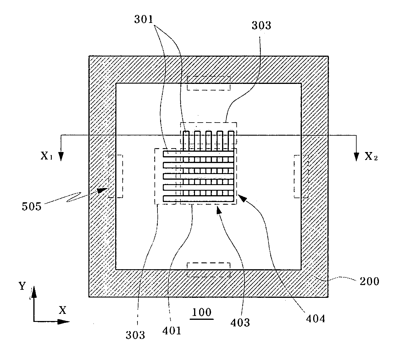
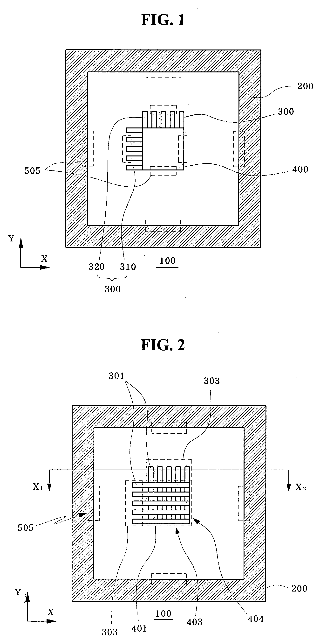
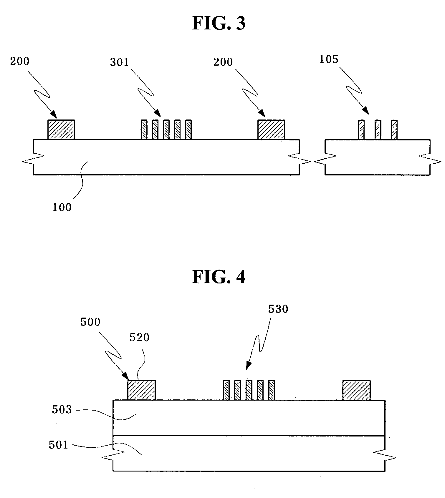
[0030]FIGS. 1 and 2 are schematic plan views illustrating a mask with a focus measurement pattern in accordance with the invention, and FIG. 3 is a schematic sectional view illustrating the mask with a focus measurement pattern in accordance with the invention.

[0031]Referring to FIG. 1 the mask according to the invention is provided with a focus measurement pattern structure on a transparent mask substrate 100, which is transferred onto a wafer. The focus measurement pattern structure includes an outer reference pattern 200 which provides a position reference for the focus measurement, and line-shaped focus measurement patterns 300 which are disposed apart from the outer reference pattern 200 and extend in two different directions.

[0032]The outer reference pattern 200 may be configured as a polygonal (e.g., rectangular) frame pattern. The outer reference pattern 2...


PUM

PropertyMeasurementUnit
widthaaaaaaaaaa
lengthaaaaaaaaaa
shapeaaaaaaaaaa

Abstract

A mask with a focus measurement pattern and a method for measuring a focus value in an exposure process using the same that are capable of improving the measurement of a focus change, wherein the mask includes an outer reference pattern which provides a position reference for focus measurement, and focus measurement patterns which are provided apart from the outer reference pattern and formed in a line shape extending in two different directions. Accordingly, the focus change caused in the exposure process can be measured by measuring the line shortening of the focus measurement patterns.

Description

CROSS-REFERENCE TO RELATED APPLICATION[0001]The priority of Korean patent application number 102006-0137140, filed on Dec. 28, 2006, which is incorporated by reference in its entirety, is claimed.BACKGROUND OF THE INVENTION[0002]The invention relates to micro-lithography and, more particularly, to a mask with a focus measurement pattern and a method for measuring a focus value in an exposure process using the same.[0003]When manufacturing an integrated circuit device or a semiconductor device, a micro-lithography process of transferring circuit patterns designed on a mask onto a wafer is performed. The micro-lithography process includes an exposure stage in which circuit patterns on a mask are transferred onto a wafer by using an exposure apparatus, and a stage performing a selective etching using an exposed resist pattern.[0004]At this time, the accurate transfer of the circuit patterns oil the mask onto the wafer depends on an extent of focus change in the exposure stage. Due to v...

Claims


Application Information

Patent Timeline
Patent Type & Authority Applications(United States)
IPC IPC(8): G03F1/00G06K9/00
CPCG03F1/14G03F7/70683G03F7/70641G03F1/44G03F1/62G03F1/68
Inventor HONG, JONG KYUN
Owner SK HYNIX INC
Why Eureka
Try Eureka