
Proximal reamer

a technology of proximal reamer and proximal reamer, which is applied in the field of orthopaedics, can solve the problems of inability to stabilize the joint, difficult to combine all these biomechanic options, and particularly difficult to disloca

Active Publication Date: 2008-07-03
DEPUY SYNTHES PROD INC
View PDF99 Cites 45 Cited by
  • Summary
  • Abstract
  • Description
  • Claims
  • Application Information

AI Technical Summary

Benefits of technology

[0022]The design of the present invention gives the surgeon the ability to remove proximal bone after the distal implant has been implanted utilizing the fixed position of the implant to support a tool to remove the proximal bone.
[0024]After a long bone, for example a hip, has been resected, you must ream distally to prepare canal for the distal stem implant in a modular distal stem and proximal body implant assembly. This reaming is done using a tapered reamer. The distal stem implant has a 3° bend to accommodate for the natural interior bow of the femoral canal in long distal stem implant configurations used in revision arthroplasty. Because of the 3° bend, proximal reaming must be separately performed to remove the bone not removed by the distal tapered reamer. Once the implant has been implanted, the surgeon may, utilizing the present invention, use the proximal end or tapered portion of the distal stem implant as a pilot shaft for the proximal reamer. A protective sleeve may be placed over the tapered portion of the distal stem component of the implant to prevent damage to the distal stem component while the proximal reaming is being performed. The next step for the surgeon, after the proximal reaming, would be to proceed with implanting the proximal body implant or a proximal body trial. A trial reduction is then performed and, if a trial reduction includes a proper implant / trial assembly selection, the corresponding implant is then inserted onto the distal stem implant.
[0031]The technical advantages of the present invention include the ability to reduce the number of steps in the surgical technique necessary to perform orthopedic surgery, for example hip implant surgery. For example, according to one aspect of the present invention a method for providing joint arthroplasty is provided. The method includes the steps of resecting an end portion of a long bone, preparing a central longitudinal opening in the canal, providing a prosthetic stem component, and installing the stem component into the opening. The method also includes the step for providing a reamer for receiving the prosthetic stem component. The reamer is positioned at least partially over the prosthetic stem component. By placing the reamer over the prosthetic stem component a separate tool is not required to guide the reamer and a prosthetic trial or other component is not required to be positioned in the canal to provide the support for the reamer. Thus the present invention provides for a reduction in the number of steps in the surgical technique for joint arthroplasty.
[0032]The technical advantages of the present invention further include a reduction in the number of instruments required to perform a joint arthroplasty, a reduced number of instruments in the instrument tray and a reduction in the related costs of the instruments. For example, and according to another aspect of the present invention, a method and apparatus for providing joint arthroplasty is provided in which the distal stem implant is implanted into the reamed bone canal without the use of a distal stem trial. Therefore, the instrument of a distal stem trial is not required in this aspect of the present invention. Thus the present invention provides for a reduced number of instruments required to perform the joint arthroplasty.
[0034]The technical advantages of the present invention further include the ability to remove bone in a form that is eccentric with the center line of the distal canal with a reamer. For example, according to another aspect of the present invention a reamer assembly is provided for reaming a proximal portion of a cavity for use in implanting a proximal body implant of a modular joint prosthesis. The reamer cooperates with a proximal portion of the distal stem implant. The reamer assembly includes a proximal reamer and a sleeve that slips over the proximal portion of the distal stem implant. The sleeve may snap into a cavity of the proximal reamer. The orthopedic implant stem has a proximal portion that is non-linear with the distal portion of the implant stem. Thus the present invention provides the ability to remove bone that is eccentric with the distal canal with a reamer. Reaming of the proximal portion of the long bone may be better than broaching the proximal portion in that bone may be too sclerotic or too weak and fragile to absorb the impaction force from broaching.

Problems solved by technology

Currently in total hip arthroplasty, a major critical concern is the instability of the joint.
Dislocation is particularly a problem in total hip arthroplasty.
The combination of all these biomechanic options is rather complex.
Improper anteversion can lead to dislocation and patient dissatisfaction.
However, it is a more challenging issue with the advent of stems with additional modularity.
Quite often the remaining bone is significantly compromised compared to a primary hip procedure.
Significant bone loss is observed, often with a lack of bone landmarks typically used for alignment.
The long stem trials do not have the transverse bolts and are thus not rotationally stable during trial reduction and therefore are not always used by the surgeon.
Currently available implants, trials and instruments result in a lengthy surgical procedure.
This lengthy procedure increases the risk of the patient's surgical complications.
Adjustments in the positioning and selection of the trial and resultant implants thus become difficult and time consuming to perform.
The reamer that prepares the distal cavity can not remove bone to provide clearance to the proximal body in a precise manner to minimize bone removal, due to the fact that the proximal body centerline of the implant is not in alignment with the distal stem centerline.
Either method requires additional bone removal that is not clinically desired.

Method used


Image

  • Proximal reamer
  • Proximal reamer
  • Proximal reamer

Examples


Embodiment Construction

[0093]Embodiments of the present invention and the advantages thereof are best understood by referring to the following descriptions and drawings, wherein like numerals are used for like and corresponding parts of the drawings.

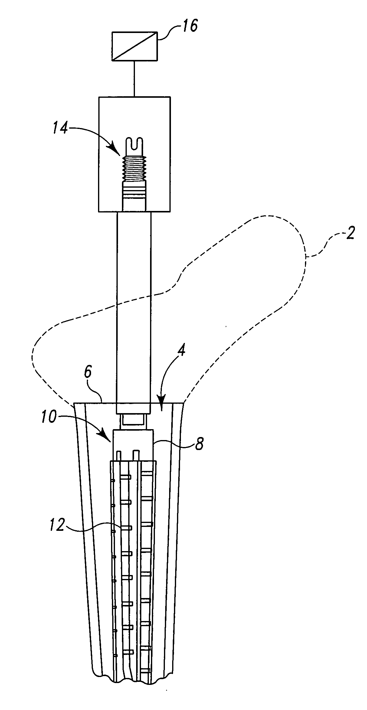
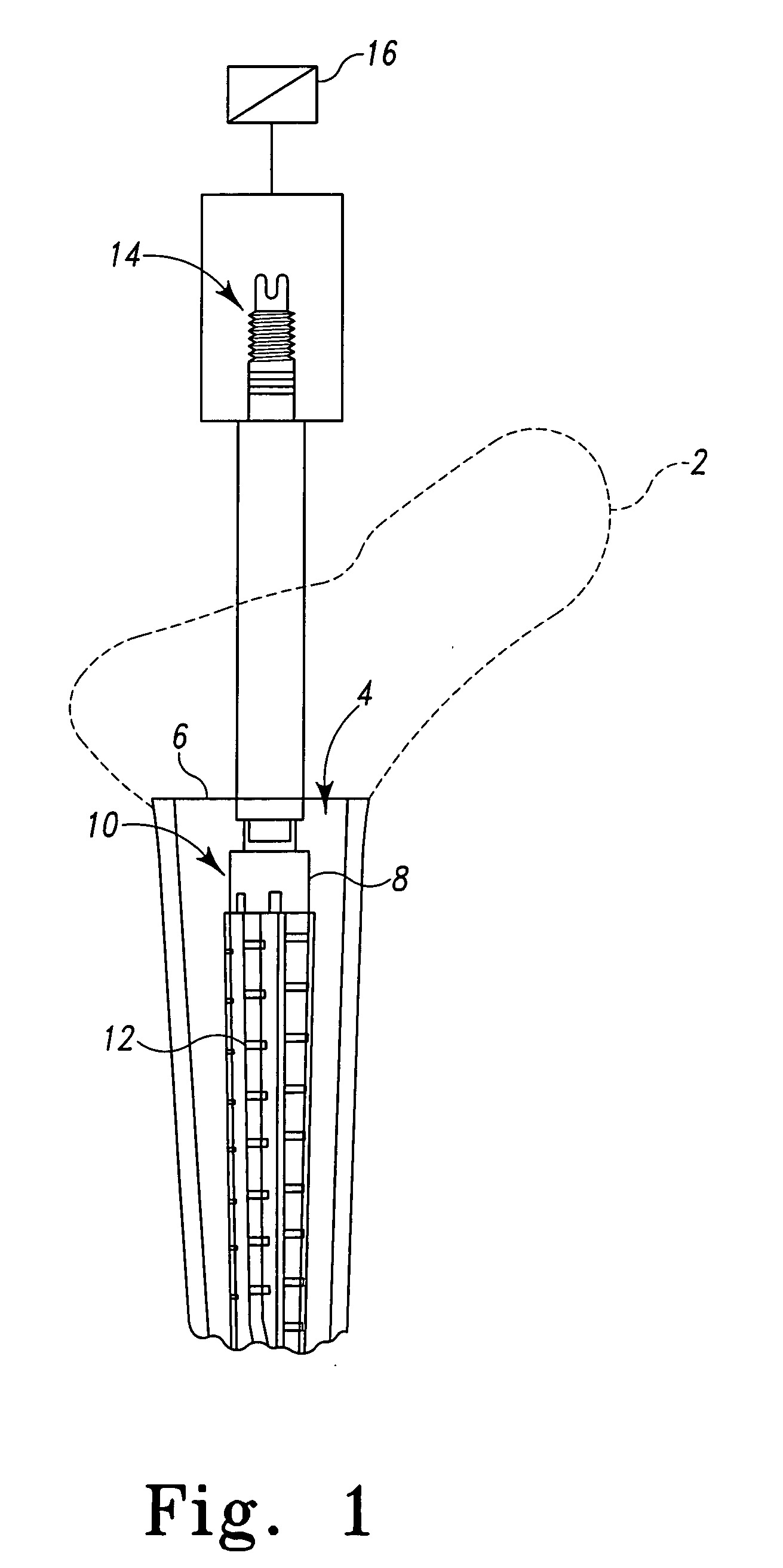
[0094]Referring now to FIG. 1 a long bone or femur 2 for use with the present invention is shown. The femur 2 includes an intermedullary canal 4 into which the prosthesis of the present invention may be inserted. The femur 2 is resected along resection line 6 by, for example, a power tool, for example, a saw. The resecting of the long bone or femur 2 exposes the intermedullary canal 4 of femur 2. A reamer 8 that may be a standard commercially available reamer is positioned in the intermedullary canal 4 of the long bone 2 to form cavity 10 for receiving an orthopedic joint implant. The reamer 8 includes a plurality of longitudinally extending flutes 12 which are used to remove bone and other biological matter from the intermedullary canal 4 to form the cavity 1...


PUM


Abstract

A reamer for reaming a proximal portion of a cavity for use in implanting a joint prosthesis is provided. The reamer is used for cooperation with a proximal portion of an orthopaedic implant component. The reamer includes a body defining a cavity formed therein for receiving at least a portion of the orthopaedic implant component. The reamer also includes a plurality of cutting edges extending outwardly from the body. The edges are adapted for cooperation with bone. The reamer also includes a stem extending from an end of the body.

Description

TECHNICAL FIELD OF THE INVENTION[0001]The present invention relates generally to the field of orthopaedics, and more particularly, to an implant for use in arthroplasty.BACKGROUND OF THE INVENTION[0002]Patients who suffer from the pain and immobility caused by osteoarthritis and rheumatoid arthritis have an option of joint replacement surgery. Joint replacement surgery is quite common and enables many individuals to function properly when it would not be otherwise possible to do so. Artificial joints are usually comprised of metal, ceramic and / or plastic components that are fixed to existing bone.[0003]Such joint replacement surgery is otherwise known as joint arthroplasty. Joint arthroplasty is a well-known surgical procedure by which a diseased and / or damaged joint is replaced with a prosthetic joint. In a typical total joint arthroplasty, the ends or distal portions of the bones adjacent to the joint are resected or a portion of the distal part of the bone is removed and the arti...

Claims


Application Information

Patent Timeline
IPC IPC(8): A61B17/00
CPCA61B17/164A61B17/1739A61F2/32A61F2/34A61F2/36A61F2/3662A61F2/367A61F2/3676A61F2/4684A61F2002/30224A61F2002/30322A61F2002/30331A61F2002/30332A61F2002/30474A61F2002/30492A61F2002/30512A61F2002/30604A61F2002/30827A61F2002/30886A61F2002/3495A61F2002/3611A61F2002/3625A61F2002/365A61F2002/366A61F2002/3674A61F2002/368A61F2002/3686A61F2220/0025A61F2220/0033A61F2230/0069A61F2250/0026A61F2310/00017A61F2310/00023A61F2310/00029A61B17/16A61B17/1668A61B17/1604A61F2/4607A61F2/4657A61F2/468A61B2017/564A61F2002/30507A61F2002/3054
Inventor DANIELS, DAVID W.CARR, JONATHAN E.SCHNIEDERS, BARRY A.MCCLEARY, LARRY G.SURMA, GABRIEL M.
Owner DEPUY SYNTHES PROD INC
Features
  • Generate Ideas
  • Intellectual Property
  • Life Sciences
  • Materials
  • Tech Scout
  • Unparalleled Data Quality
  • Higher Quality Content
  • 60% Fewer Hallucinations
Learn More