Loop heat pipe with flat evaportor

a technology of evaporator and loop pipe, which is applied in the direction of lighting and heating apparatus, cooling/ventilation/heating modification, semiconductor devices, etc., can solve the problems of non-uniform distribution, easy formation of hot spots, damage to semiconductor chips, etc., to improve entertainment limits, reduce the drawback of performance, and improve the effect of performan

Inactive Publication Date: 2008-07-10
TAMKANG UNIVERSITY
View PDF18 Cites 79 Cited by
  • Summary
  • Abstract
  • Description
  • Claims
  • Application Information

AI Technical Summary

Benefits of technology

[0013]The present invention provides a miniature loop heat pipe with flat evaporator, which can be used in a notebook computer to alleviate the drawback of reducing performance caused by bending of the traditional tubular heat pipe, and also improves the entertainment limit caused by the small size of the heat pipe. Employing flexible conduit in a limited space is advantageous in providing flexibility of use of space inside a notebook computer.
[0014]The loop heat pipe of the present invention demonstrates excellent heat removal performance, which is far superior to the conventional water cooling techniques, and does not suffer troubles caused by spillage of water that often damages electronics. Further, the loop heat pipe of the present invention comprises conduits that are extended from a heat source to a remote location so that the drawbacks of incapability of long distance transfer of heat and un-bendability suffered by the conventional heat pipe is completely removed by the present invention. Water would not spill to the heat source device and would not cause the short circuit to the heat source device. Theoretically, thermal performance of the loop heat pipe can be enhanced, as compared to the known devices of the same purposes.
[0015]The conventional plate heat pipes are often used in military and/or aerospace applications for their high costs. The present invention provides a loop...

Problems solved by technology

Thus, heat flux on the surface of a package is generally distributed in a non-uniform manner, and hot spots are easily formed.
This makes the thermal stress distribution non-uniform and causes damage to the semiconductor chip.
Those heat dissipation modes that are of high costs and consequently high performance may not be fit for computers, which are generally low-cost devices operated at high power.
Heat pipes that are used for heat dissipation of electronic devices are often of a small contact with the heat generating parts and the tubular configuration of the heat pipes also impose limitation to the shape of the heat pipe in actual practi...

Method used


Image

  • Loop heat pipe with flat evaportor
  • Loop heat pipe with flat evaportor
  • Loop heat pipe with flat evaportor

Examples


Embodiment Construction

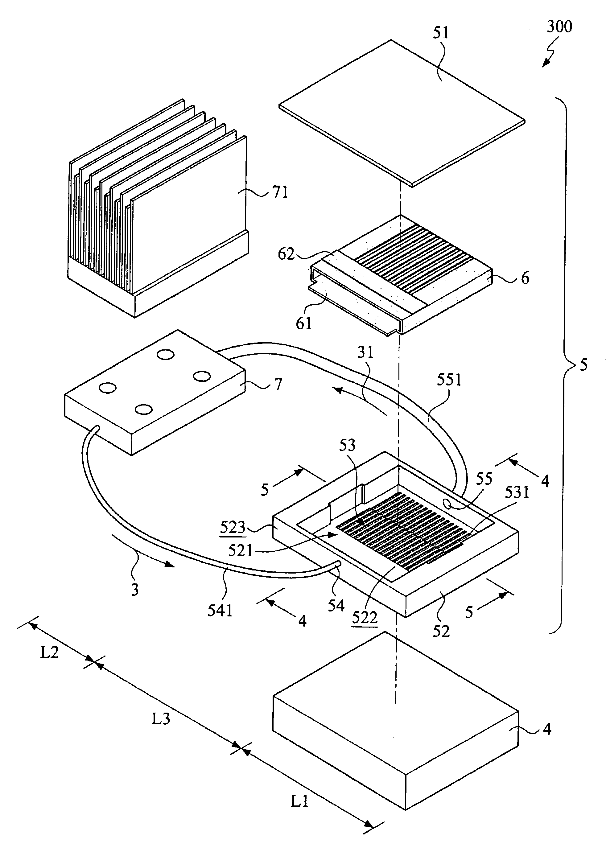
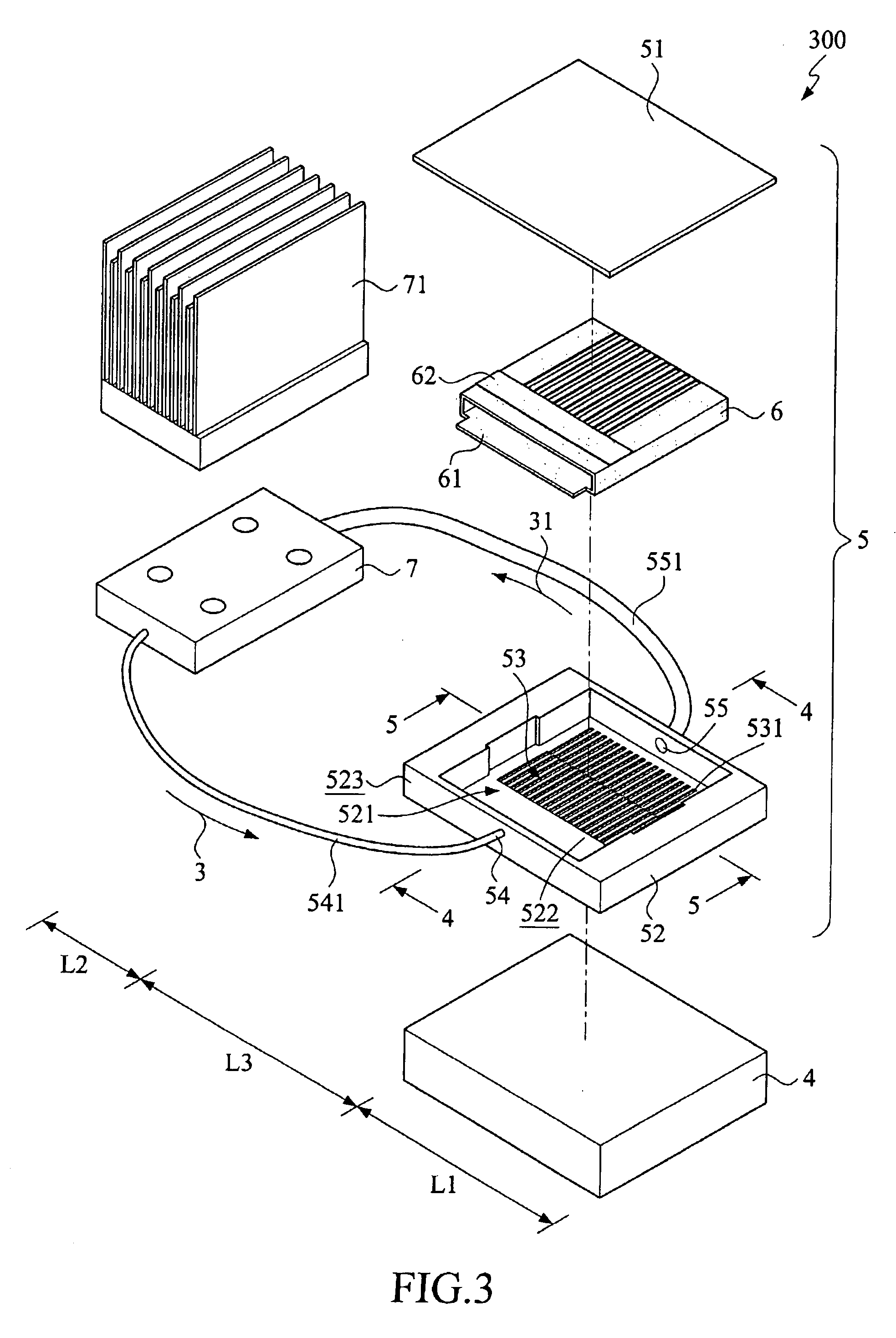
[0027]With reference to the drawings and in particular to FIGS. 3-5, which show, respectively, an exploded view of a loop heat pipe with flat evaporator constructed in accordance with the present invention and cross-sectional views taken along lines 4-4 and 5-5 of FIG. 3, the loop heat pipe of the present invention, generally designated with reference numeral 300, comprises an evaporation section L1, a condensation section L2, and a transportation section L3 connected between the evaporation section L1 and the condensation section L2.

[0028]The evaporation section L1 is arranged to contain a heat source 4 therein and also comprises an enclosed containment structure 5 disposed on the heat source 4. The enclosed containment structure 5 comprises a lid 51 and a container 52, defining therebetween an enclosed containment space 521 for receiving a working fluid 3. The enclosed containment space 521 comprises a channel structure 53, a capillary structure 6, a liquid inlet 54, and a gas out...


PUM


Abstract

A loop heat pipe with flat evaporator includes an evaporation section, a condensation section, and a transportation section connected between the evaporation section and the condensation section. The evaporation section includes a heat source, an enclosed containment structure, and a capillary structure. The enclosed containment structure is positionable on the heat source and forms an enclosed containment space which receives a working fluid and has a bottom in which a channel structure is formed and further forms a liquid inlet and a gas outlet in a circumferential wall thereof the container to respectively connect a liquid passage and a gas passage so that when the working fluid is heated by the heat source to become vapor, the vapor moves through the gas outlet and the gas passage to a condensing device provided in the condensation section where the vapor is cooled and converted back to the liquid form of the working fluid that is then guided through the liquid passage back to the enclosed containment space for next cycle.

Description

FIELD OF THE INVENTION[0001]The present invention relates to a loop heat pipe, and in particular to a loop heat pipe with a flat evaporator.BACKGROUND OF THE INVENTION[0002]With the development of semiconductor related techniques, the number of leads in a semiconductor chip is continuously increased. To accommodate the increased number of leads, the surface area of a packaged semiconductor device is often several times of the related die area. Thus, heat flux on the surface of a package is generally distributed in a non-uniform manner, and hot spots are easily formed. This makes the thermal stress distribution non-uniform and causes damage to the semiconductor chip. Heat pipe is one of the most powerful way to remove heat from a heat-generating device to a heat dissipation device, and heat is dissipated at the heat dissipation device. One of the most common applications of the heat pipe is the electronic devices, such as a notebook computer.[0003]The currently known modes of heat di...

Claims


Application Information

Patent Timeline
IPC IPC(8): H05K7/20F28D15/00
CPCF28D15/0266F28D15/043F28D15/046H01L23/427H01L2924/0002H01L23/473H01L2924/00
Inventor KANG, SHUNG-WENTSAI, MENG-CHANG
Owner TAMKANG UNIVERSITY
Why Eureka
Try Eureka