Heat Exchanger

a technology of heat exchanger and heat exchanger plate, which is applied in the direction of light and heating apparatus, machines/engines, laminated elements, etc., can solve the problems of fluid stagnation, cumbersome assembly, and prone to leakage at the brazed parts, so as to improve air tightness and liquid tightness, the effect of reducing the number of joints

Inactive Publication Date: 2008-07-10
T RAD CO LTD
View PDF9 Cites 49 Cited by
  • Summary
  • Abstract
  • Description
  • Claims
  • Application Information

AI Technical Summary

Benefits of technology

[0021]Moreover, the number of joints decreases and air-tightness and liquid-tightness improve, and it is possible to provide a heat exchanger that is compact and excellent in performance. Further, a pair of projecting stripes 3a is formed in each of the first flow channels 3 at the ports, thus it is possible to prevent cooling water from stagnating in the vicinity of the ports, then gaps 3c are provided between the pair of the projecting stripes 3a, therefore the cooling water flows also through the gaps 3c, and hence the cooling water flows evenly in each part and the heat exchange is accelerated.
[0022]In the above configuration, it is possible to: vary the gaps 3c between the projecting stripes 3a along the longitudinal direction; and finely adjust the uniform flow of the cooling water in response to various conditions.
[0023]Yet further, by configuring the gaps 3c at intermediate portions of the projecting stripes

Problems solved by technology

The drawbacks of such a heat exchanger as an EGR cooler or the like have been that: the number of parts is large, which makes assembling cumbersome; and the number of brazed portions of each component increases, which causes leakage to tend to occur at the brazed portions.
Moreover, it has

Method used


Image

  • Heat Exchanger
  • Heat Exchanger
  • Heat Exchanger

Examples


Embodiment Construction

[0036]Next, embodiments according to the present invention will be described in reference to drawings.

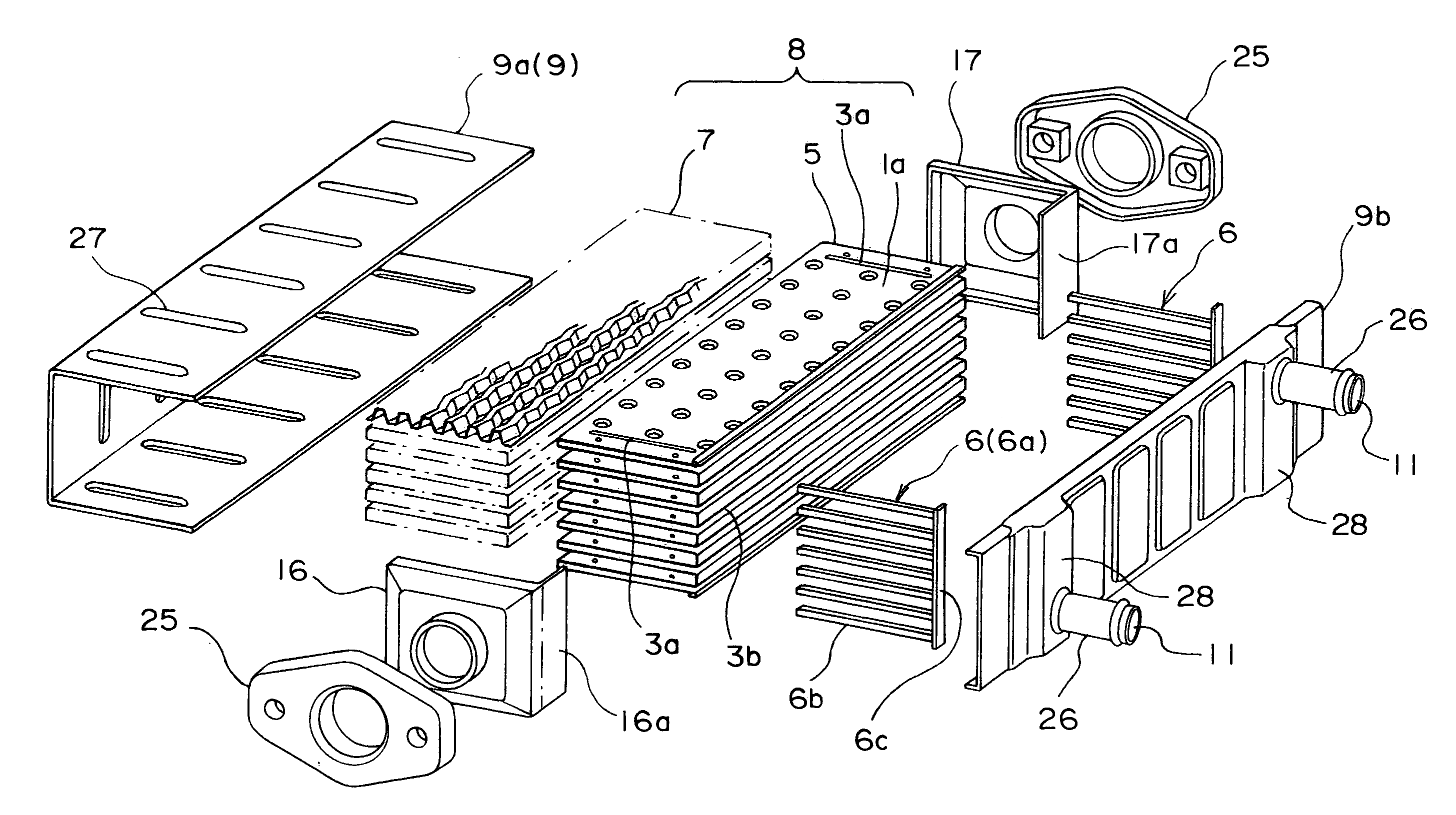
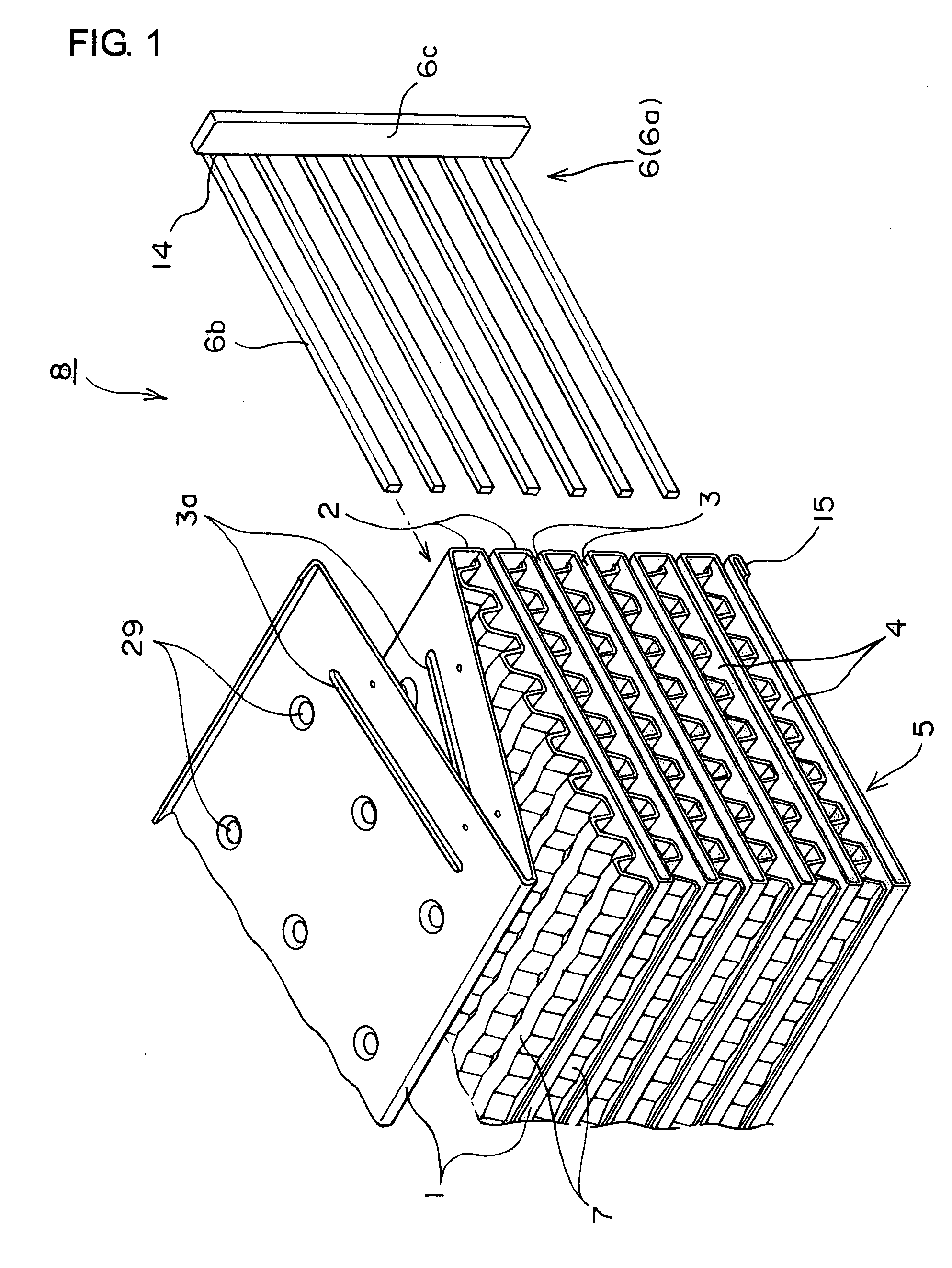
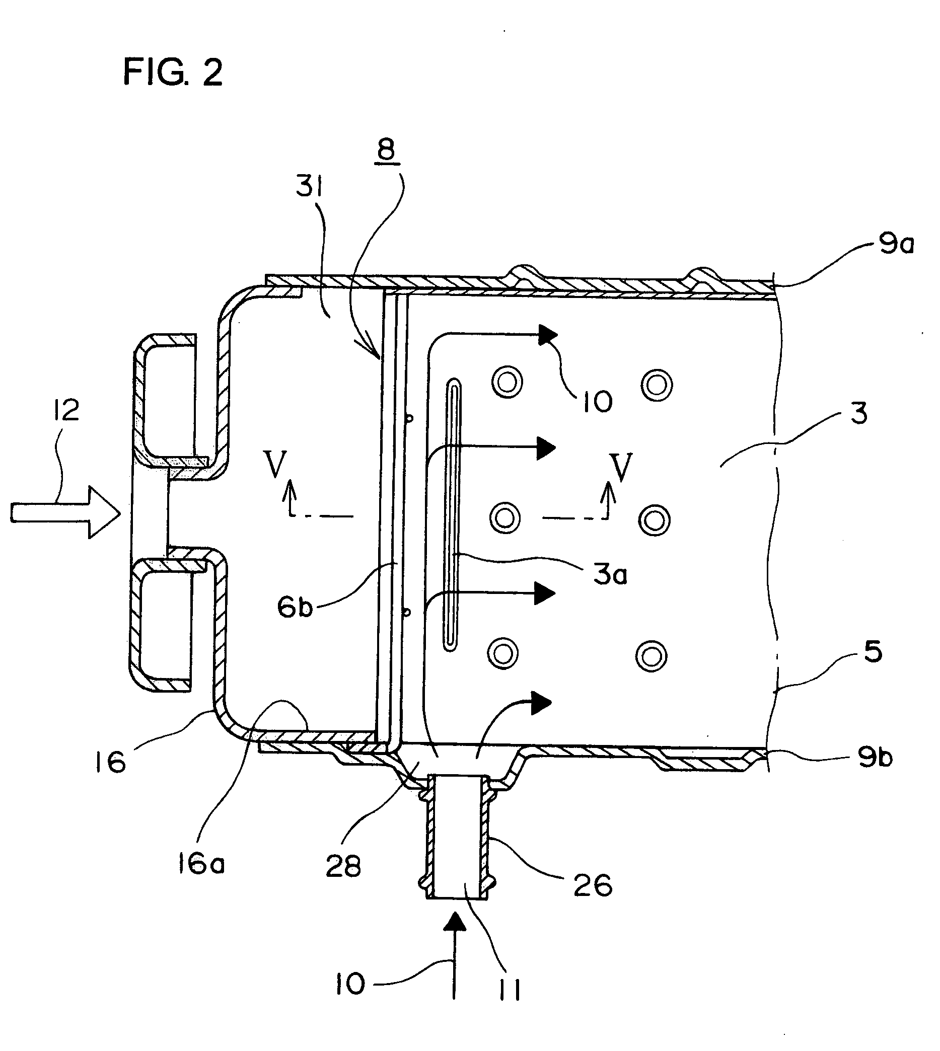
[0037]FIG. 1 is an exploded perspective view showing a substantial part of a heat exchanger according to the present invention, FIG. 2 is a sectional view showing the state of the assembling thereof, FIG. 3 is an exploded perspective view showing the whole heat exchanger, FIG. 4 is a perspective view showing the assembled state thereof, FIG. 5 is a schematic sectional view of a substantial part taken on line V-V of FIG. 2, and FIG. 6 is a perspective view thereof.

[0038]The heat exchanger has a core body 5, a large number of fins 7, a casing 9, a pair of header end lids 16 and 17, and a pair of slit blocks 6 as shown in FIG. 3.

[0039]The core body 5, as shown in FIG. 1: is configured by turning up and bending a strip-shaped metal plate in a fanfold manner and forming turned-up end edges 1 and 2 alternately at one end and then the other end of a rectangular planar portion 1a; and has f...


PUM


Abstract

In a heat exchanger used for an EGR cooler or the like, in order to provide a heat exchanger that has a small number of parts, is assembled easily, can flow cooling water evenly at each part, and does not cause partial boiling, a strip-shaped metal plate is turned up and bent in a fanfold manner, flat first flow channels 3 and second flow channels 4 are formed alternately, both the ends of the first flow channels 3 are closed with slit blocks 6, projecting stripes 3a are bent and formed at the positions of ports 11 for the cooling water 10 in proximity to the slit blocks 6, and gaps 3c are formed between respective paired projecting stripes 3a.

Description

BACKGROUND OF THE INVENTION[0001]The present invention relates to a heat exchanger having a simple structure and being easily produced, which can be used as a heat exchanger (EGR cooler) used in an exhaust gas recirculation apparatus of an automobile or another heat exchanger.[0002]A conventional EGR cooler comprises an assembly of a large number of flat tubes or plates, a large number of fins, a casing, and a header, wherein cooling water is made to flow on the side of the casing and an exhaust gas is made to flow in the interior of the flat tubes or the like as the invention disclosed in Japanese Unexamined Patent Publication No. 2003-90693 for example.[0003]The drawbacks of such a heat exchanger as an EGR cooler or the like have been that: the number of parts is large, which makes assembling cumbersome; and the number of brazed portions of each component increases, which causes leakage to tend to occur at the brazed portions. Moreover, it has been feared that the portions where a...

Claims


Application Information

Patent Timeline
IPC IPC(8): F28D7/00
CPCF02M25/0737F28D9/0025Y02T10/121F28F3/04F28F9/0265F28D21/0003F28F2220/00F02M26/32
Inventor NAKAMURA, YOICHI
Owner T RAD CO LTD
Why Eureka
Try Eureka