

Power-generator control apparatus for addressing occurrence of voltage transient
a technology of voltage transient and control apparatus, which is applied in the direction of electric generator control, dynamo-electric converter control, transportation and packaging, etc., can solve the problem of difficulty in stably adjusting the output of the alternator
- Summary
- Abstract
- Description
- Claims
- Application Information
AI Technical Summary
Benefits of technology
Problems solved by technology
Method used
Image

Examples
first embodiment
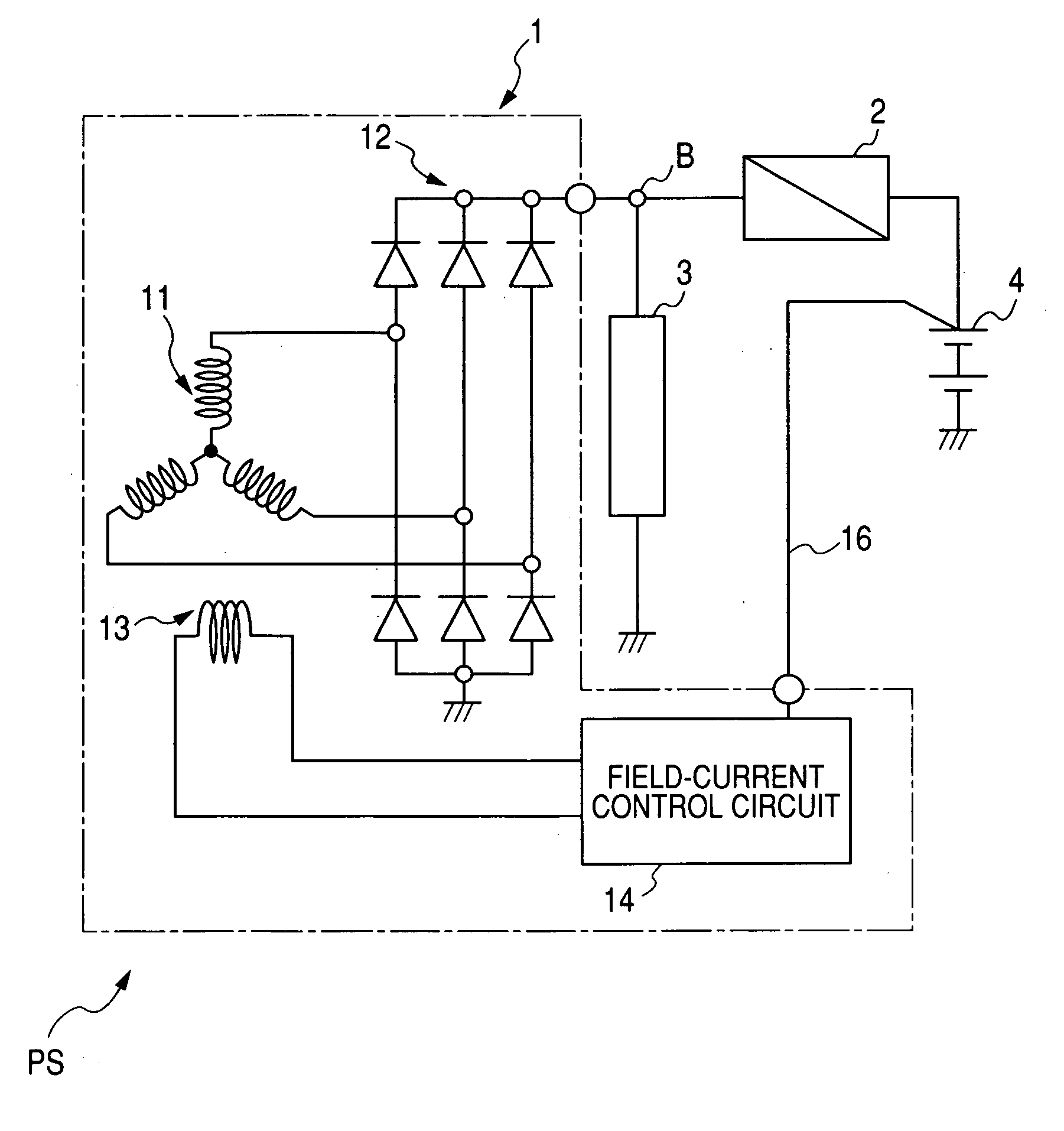
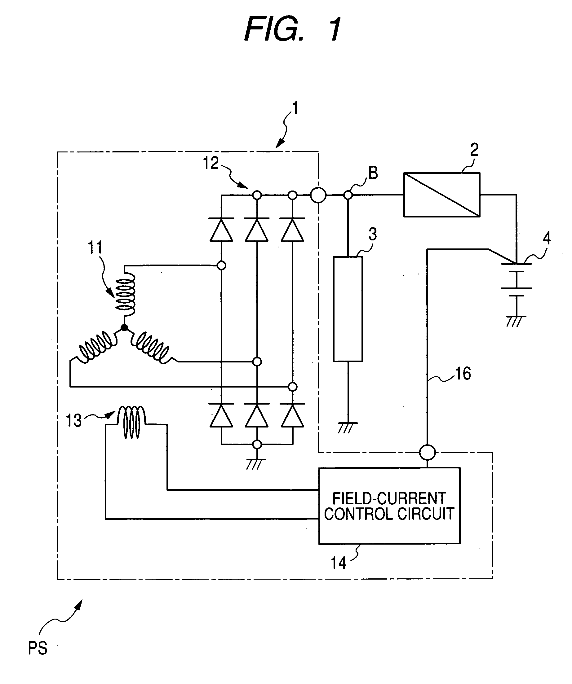
[0038]Referring to FIG. 1, there is provided a power supply system PS installed in, for example, a motor vehicle and equipped with a power-generator control apparatus according to a first embodiment of the present invention.
[0039]The power supply system PS includes an alternator 1 as an example of power-generators, a DC to DC converter 2, electrical loads 3, and an in-vehicle battery 4.
[0040]The alternator 1 has an output terminal B to which an input terminal of the DC to DC converter 2 is connected. An output terminal of the DC to DC converter 2 is connected to a positive terminal of the battery 4 whose negative terminal is grounded. The alternator 1 works to output a high DC voltage via the output terminal B.
[0041]The DC to DC converter 2 for example consists of:
[0042]a smoothing capacitor connected in parallel to the input terminal thereof for smoothing the DC voltage output from the alternator 1;
[0043]a first converter for converting the output DC voltage into an AC voltage;
[004...
second embodiment
[0098]FIG. 5 is a circuit diagram schematically illustrating the structure of a power supply system PS1 according to a second embodiment of the present invention. Like parts between the first and second embodiments, to which like reference characters are assigned, are omitted or simplified in description.
[0099]As illustrated in FIG. 5, the power supply system PS1 includes a three-phase brushless motor 6, and a three-phase inverter 5 having an input terminal connected to the output terminal B of the alternator 1 and having three-phase output lines connected to the three-phase brushless motor 6.
[0100]The three-phase inverter 5 works to receive the DC voltage output from the alternator 1, smooth the received DC voltage by a smoothing capacitor 5a connected in parallel to the input terminal thereof, convert the smoothed DC voltage into a three-phase AC voltage, and to supply the converted three-phase AC voltage to the three-phase brushless motor 6.
[0101]The capacitance of the smoothing ...
third embodiment
[0107]FIG. 6 is a circuit diagram schematically illustrating the structure of a field-current control circuit according to a third embodiment of the present invention. Like parts between the first and third embodiments, to which like reference characters are assigned, are omitted or simplified in description.
[0108]As illustrated in FIG. 6, a field-current control circuit 14B is provided with a constant voltage diode 22 connected to the field current attenuation line 15 in parallel to the capacitor 21.
[0109]The constant voltage diode 22 allows the upper limit of the charged voltage in the capacitor 21 to be determined to a constant threshold voltage Vz of the constant voltage diode 22.
[0110]Because increase in the charged voltage in the capacitor 21 is restricted to be equal to or lower than the upper limit, it is possible to reduce a rated voltage of the capacitor 21.
[0111]In addition, in the third embodiment, the damping time t is represented by the following equation:
If≈I0−(Vz / L)×...
PUM
 Abstract
Description
Claims
Application Information