Multiple Channel Interferometric Surface Contour Measurement System

a multi-channel, surface contour technology, applied in the direction of instruments, optical elements, mountings, etc., can solve the problems of grating into the beam path affecting the stability and therefore the accuracy of measurement data, etc., to reduce the change of orientation and improve the stability of orientation

Active Publication Date: 2008-07-10
DIMENSIONAL PHOTONICS INT
View PDF14 Cites 11 Cited by
  • Summary
  • Abstract
  • Description
  • Claims
  • Application Information

AI Technical Summary

Benefits of technology

[0008]In another aspect, the invention features a crossbar for improved orientation stability between two system components in an interferometric measurement system. The crossbar includes an outer cylindrical tube, an inner cylindrical tube and a pair of O-rings. The outer cylindrical tube has a tube axis, an inner surface and two ends. The inner cylindrical tube has a tube axis collinear with the tube axis of the outer tube and also has an outer surface and two ends. The inner cylindrical tube is disposed inside the outer tube and extends outside the two ends of the outer cylindrical tube. Each end of the inner cylindrical tube is adapted for attachment to one of the system components. The O-rings are disposed between the inner surface of the outer cylindrical tube and the outer surface of the inner cylindrical tube. Each O-ring is disposed along a length of the inner cylindrical tube at a predetermined position to reduce changes in the orientation between the two system components as the crossbar is reoriented.

Problems solved by technology

This multiplexing of different gratings into the beam path poses many challenges.
Moving different gratings into the beam path and shifting each grating to implement phase shifts generally requires multiple mechanical components that add weight, size, complexity and cost to the system.
The frequent movement of components affects the stability and therefore the accuracy of the measurement data.
Moreover, measuring the displacement of a diffraction grating during the phase shift process with sufficient precision and accuracy can require expensive measurement components such as capacitance gauges.
Other system components can limit the applications for the system.
For example, the focusing objective and spatial filter are used for multiple gratings and, therefore, their optical parameters are not optimal for the individual gratings.
Moreover, the depth of field of the camera can limit the maximum spatial frequency of the projected fringe pattern, thereby limiting the measurement resolution.
Noise sources also typically limit the measurement data.
Speckle results in part from the roughness of the object surface.
These contributions interfere with one another to produce complex intensity variations across the surface of the object as viewed from a distance.
Shot noise contributions from the individual detectors in the camera can further limit the accuracy of measurement data.

Method used


Image

  • Multiple Channel Interferometric Surface Contour Measurement System
  • Multiple Channel Interferometric Surface Contour Measurement System
  • Multiple Channel Interferometric Surface Contour Measurement System

Examples


Embodiment Construction

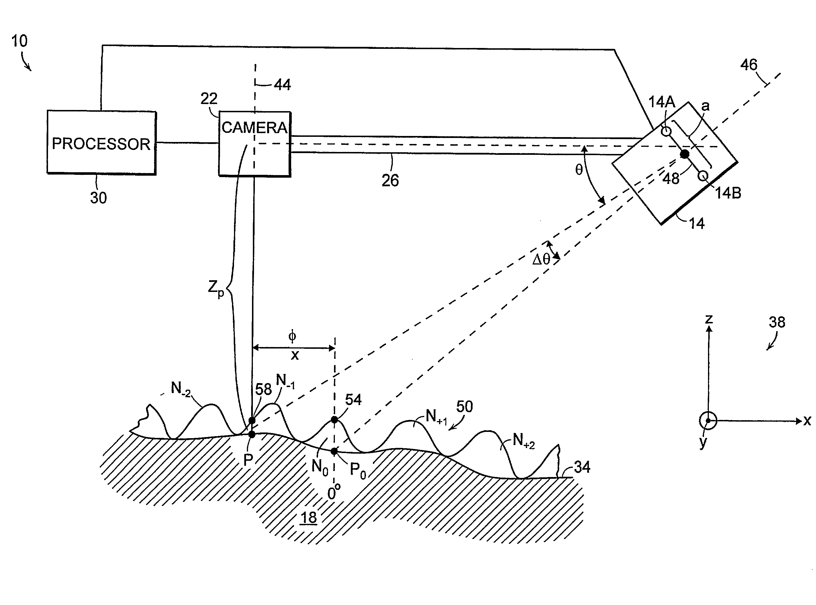
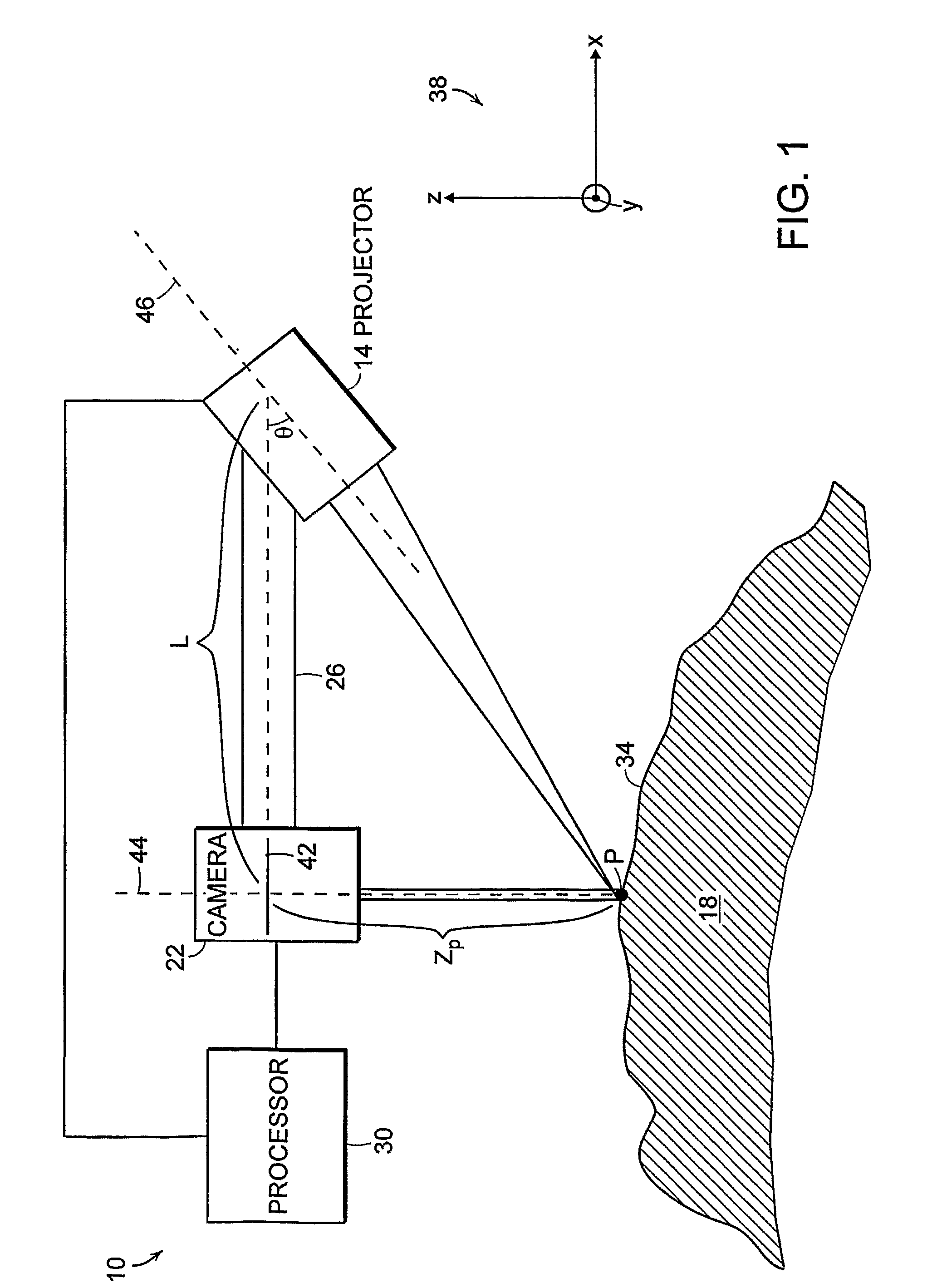
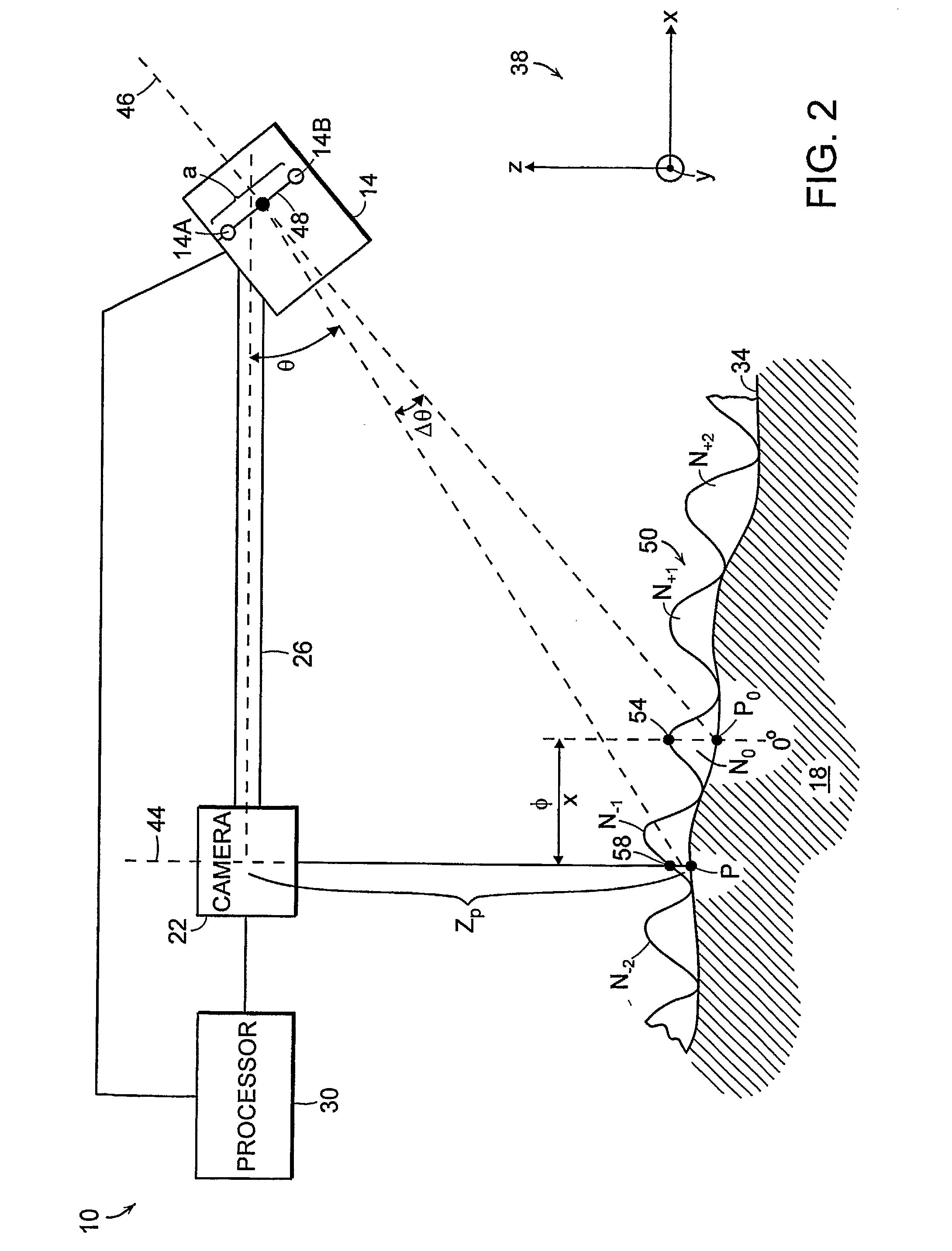
[0023]In brief overview, the present invention relates to a multiple channel interferometric surface contour measurement system. The measurement system includes a multiple channel interferometer projector, a digital camera and a processor. The projector includes two or more interferometer channels and each interferometer channel has an optical axis spatially separate from the optical axes of the other channels. Each channel projects a fringe pattern onto the surface of an object to be measured. As used herein, a digital camera means an electronic imaging device or system that provides digital image data indicative of intensity as a function of image position. The digital camera acquires image data of the fringe patterns projected on the object surface. The processor communicates with the multiple channel interferometer projector and the digital camera. Signal sent from the processor to the projector control the projection of the fringe patterns of different spatial frequencies and t...


PUM

PropertyMeasurementUnit
weightaaaaaaaaaa
diameteraaaaaaaaaa
diameteraaaaaaaaaa

Abstract

Described is a multiple channel interferometric surface contour measurement system. The measurement system includes a multiple channel interferometer projector, a digital camera and a processor. The projector includes two or more interferometer channels. Each channel has an optical axis spatially separate from the optical axes of the other channels. Each channel projects a fringe pattern onto the surface of an object to be measured. Image data for the fringe patterns projected on the object surface are acquired by the digital camera. The processor controls the projection of the fringe patterns of different spatial frequencies, adjusts the phase of each fringe pattern and generates surface contour data in response to the camera image data. The multiple channel interferometric surface contour measurement system provides numerous advantages over conventional single channel interferometric systems, including reduced sensitivity to optical noise, improved stability and increased measurement accuracy.

Description

RELATED APPLICATIONS[0001]This application claims the benefit of the earlier filing date of U.S. Provisional Patent Application Ser. No. 60 / 669,039, filed Apr. 6, 2005, titled “Multiple Channel Interferometric Surface Contour Measurement Methods and Apparatus,” the entirety of which is incorporated herein by reference.FIELD OF THE INVENTION[0002]The invention relates generally to the measurement of surface contours and more particularly to a non-contact interferometric system and method for the measurement of surface contours.BACKGROUND OF THE INVENTION[0003]Surface measurement systems are used in a variety of applications to generate three dimensional surface data of objects. Such systems are employed at various stages in the fabrication and assembly of complex objects across a variety of industries to ensure that the shape and size of the objects meet strict manufacturing tolerances.[0004]Interferometric surface measurement systems have been developed which permit measurements of ...

Claims


Application Information

Patent Timeline
Patent Type & Authority Applications(United States)
IPC IPC(8): G01C11/12G02B27/00G02B7/00G01N21/00
CPCG01B11/2527G01B11/2441
Inventor DILLON, ROBERT F.JUDELL, NEILQIAN, YIZHU, YUQINGACKERSON, D. SCOTTSINGH, GURPREET
Owner DIMENSIONAL PHOTONICS INT
Why Eureka
Try Eureka