Optical parametric amplifier

an optical parametric amplifier and amplifier technology, applied in optics, instruments, electromagnetic transmission, etc., can solve the problems of limiting the amplification band of the actual optical fiber amplifier, the influence of the reduction of the optical s/n ratio due to the addition of amplified spontaneous emission (ase) is severe, and the effect of reducing the noise of the ase is small, extending the amplification band, and favorable noise characteristics

Active Publication Date: 2008-07-10
FUJITSU LTD
View PDF23 Cites 12 Cited by
  • Summary
  • Abstract
  • Description
  • Claims
  • Application Information

AI Technical Summary

Benefits of technology

[0013]According to the abovementioned optical parametric amplifier of the present invention, due to the optical parametric amplification effect by means of the pumping light which is amplified by the first optical amplifying section using the conventional practical optical amplifier, signal light having a wavelength outside of the amplification range of the first optical

Problems solved by technology

One large problem at present is that there is a limit to the amplification band of the actual optical fiber amplifier.
In order to amplifying bands other than the C- and L-bands, there has been proposed an optical fiber amplifier or the like which is doped with a material other than Er3+, however the present situation is that this has not yet been obtained the feasibility of an EDFA.
Furthermore, in the EDFA, the noise figure is limited to 5 to 6 dB or thereabove, so that there is also the problem that the influence of the reduction in optical S/N ratio due to the added amplified spontaneous emission (ASE) is severe.
However, the above conventional optical Raman amplifier is a gain-distributed type optical amplifier which uses a part o

Method used


Image

  • Optical parametric amplifier
  • Optical parametric amplifier
  • Optical parametric amplifier

Examples


first embodiment

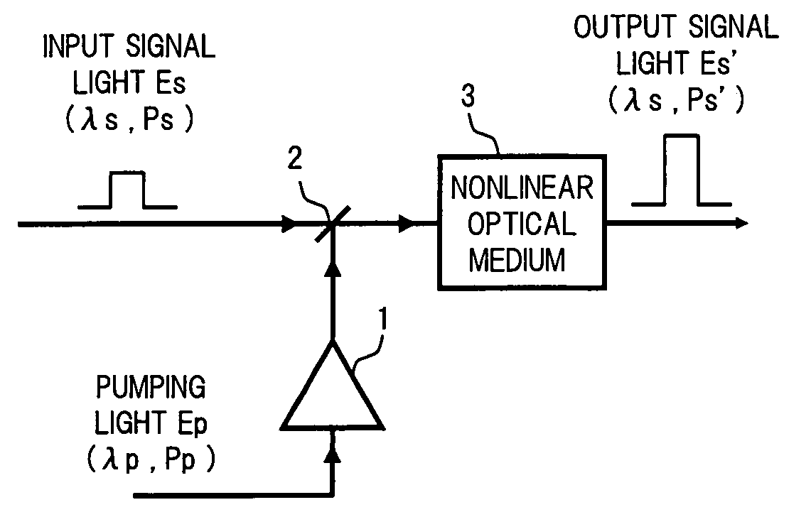
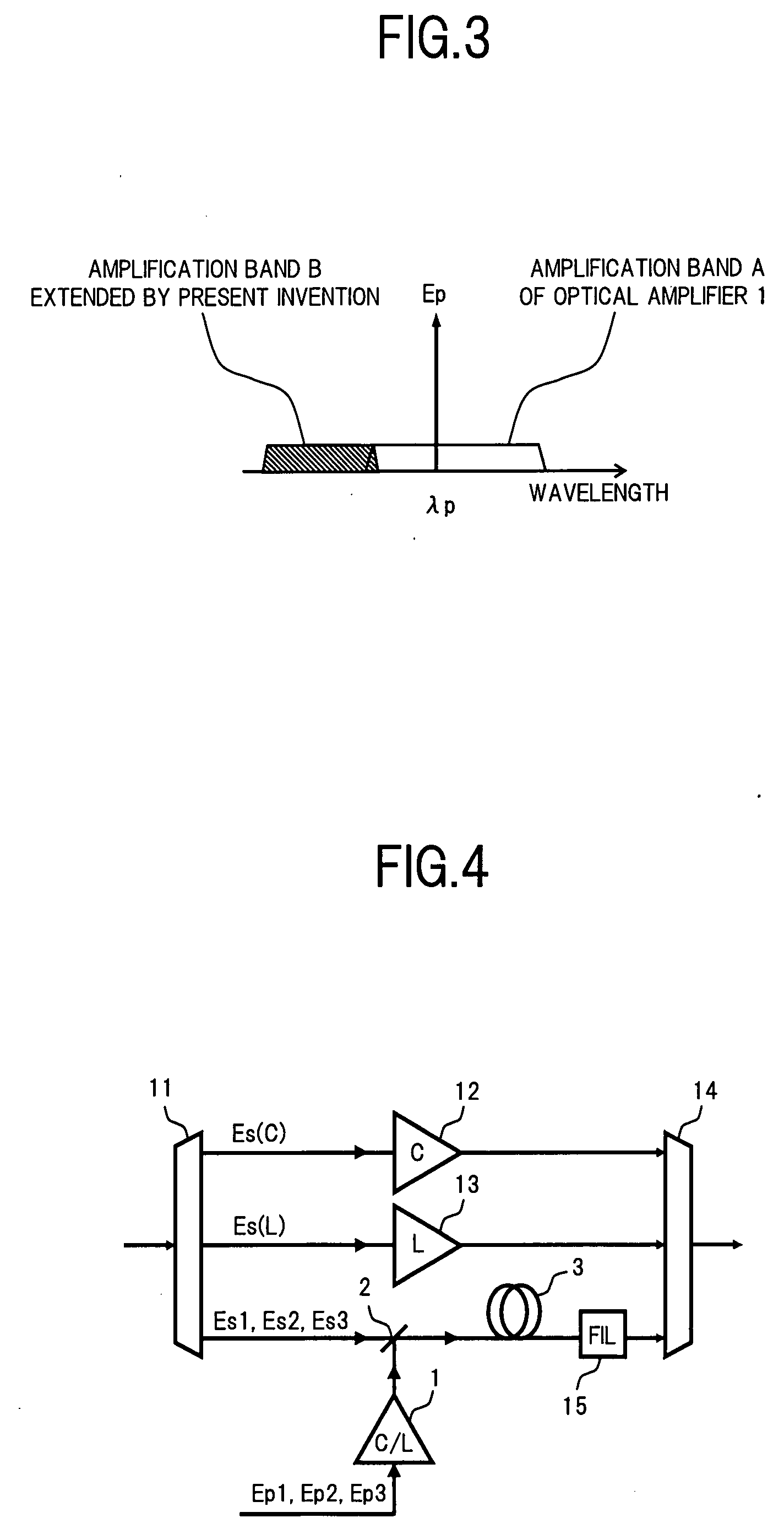
[0045]FIG. 4 is a diagram showing a configuration of an optical parametric amplifier according to the present invention.

[0046]In FIG. 4, the optical parametric amplifier of this embodiment uses the basic configuration as shown before in FIG. 1, and is configured so as to extend the amplification band of the conventional EDFA corresponding to the C- and L-bands. More specifically, in the present optical parametric amplifier, the input WDM signal light is applied to a branching filter 11, and is branched into a signal light Es (C) of C-band, a signal light Es (L) of L-band, and signal lights Es1, Es2 and Es3 outside of the C- and L-bands. To the output port corresponding to the C-band of the branching filter 11 is connected the input port of the C-band EDFA 12. Furthermore, to the output port corresponding to the L-band of the branching filter 11 is connected the input port of the L-band EDFA 13. Moreover, to the output port corresponding to other than the C- and L-bands is connected ...

second embodiment

[0053]Next is a description of the present invention.

[0054]FIG. 6 is a diagram showing a configuration of the second embodiment of an optical parametric amplifier according to the present invention.

[0055]In FIG. 6, the optical parametric amplifier of this embodiment is one which uses the basic configuration shown before in FIG. 1, to increase the gain with respect to the signal light of a specific wavelength in the conventional optical amplifier. More specifically, in this optical parametric amplifier, the input signal light Es is applied to a conventional optical amplifier 16 such as an EDFA. This optical amplifier 16 is basically the same as the optical amplifier 1 to which the pumping light Ep is input. Here the wavelength λs of the signal light Es is set to a wavelength which is different to the wavelength λp of the pumping light Ep in the amplification band of the optical amplifier 16. The signal light Es amplified by the optical amplifier 16 is applied to the signal light inpu...

third embodiment

[0058]Next is a description of the present invention.

[0059]FIG. 8 is a diagram showing a configuration of the third embodiment of an optical parametric amplifier according to the present invention.

[0060]In FIG. 8, the optical parametric amplifier of this embodiment is an application example for where in the basic configuration shown before in FIG. 1, control of the polarization and power of the signal light and the pumping light is performed so as to produce the nonlinear optical effect at an optimum state.

[0061]More specifically, in this optical parametric amplifier, a polarization controller 21 for controlling the polarization of the input signal light Es, is connected to the signal light input port of a multiplexer 2. Furthermore, a polarization controller 22 for controlling the polarization of the pumping light Ep, is connected to the input port of an optical amplifier 1. Moreover, a power controller 23 (for example a variable optical attenuator or the like) for controlling the ...


PUM


Abstract

In an optical parametric amplifier of the invention, pumping light which is amplified using a practical optical amplifier such as an EDFA is supplied together with signal light having a wavelength outside the amplification band of the optical amplifier, to a nonlinear optical medium via a multiplexer, to thereby amplify the signal light by an optical parametric amplification effect due to the pumping light in the nonlinear optical medium. As a result, the amplification band of a practical optical amplifier such as an EDFA, can be extended, and the noise characteristics can be improved.

Description

BACKGROUND OF THE INVENTION[0001]1. Field of the Invention[0002]The present invention relates to technology for amplifying light using a nonlinear optical effect, and in particular relates to an optical parametric amplifier which amplifies signal light using an optical parametric effect which is produced by four wave mixing or the like.[0003]2. Background Art[0004]In previous and present optical communication systems, a single wavelength transmission system of 10 Gb / s, or a wavelength-division multiplexed (WDM) transmission system have been developed which compensate for a decay in the signal light power due to losses of the transmission path fiber, by means of an optical amplifier such as an optical fiber amplifier.[0005]One large problem at present is that there is a limit to the amplification band of the actual optical fiber amplifier. More specifically, in an erbium (Er3+) doped fiber amplifier (EDFA), the amplifying range in the C-band in the vicinity of 1535 nm to 1565 nm, and...

Claims


Application Information

Patent Timeline
IPC IPC(8): H04B10/12G02F1/37
CPCG02F1/3536G02F1/395H04B10/2912G02F2203/06G02F2001/392G02F1/392
Inventor WATANABE, SHIGEKI
Owner FUJITSU LTD
Why Eureka
Try Eureka