Non-imaging facet based optics

a facet-based, optical concentrator technology, applied in the direction of optical elements, lighting and heating apparatuses, instruments, etc., can solve the problems of patents, inability to anticipate, teach, or show in any way, substantially in error with respect to the physical process available to the designer of a light concentrator

Inactive Publication Date: 2008-07-10
WEISS COREY A
View PDF17 Cites 39 Cited by
  • Summary
  • Abstract
  • Description
  • Claims
  • Application Information

AI Technical Summary

Benefits of technology

[0046](o) to provide a non-imaging lens that has durability due to its one material shaped form design.
[0047]“Acceptance Solid Angle” as used herein refers to the maximum half-angle subtended by a cone of rays having an apex at a specific point on the input aperture of an optical device.
[0048]“Bottom Focal Region (BFR)” as used herein refers to a concentrator's focal region being substantially near the bottom surface of a concentrating device.
[0049]“Collection” as used herein refers to the optical process of gathering solar energy into an optical system. It is separate and distinct from aggregation, concentration, distribution, and energy conversion processes.
[0050]“Concentration” as used herein refers to the optical process of increasing the flux, or flow, of light through a given area. In solar applications it is often given in terms of the number of suns of equivalent flux, where unity concentration or one sun of concentration is equivalent to 1000 Watts per square meter peak. It is separate and distinct from collection, aggregation, distribution, and energy conversion processes.
[0051]“Distribution” as used herein refers to the process of routing light, which is passing through a common input cross sectional area, and guiding it to a common output cross sectional area. It is separate and distinct from aggregation, collection, and concentration.

Problems solved by technology

The physical processes that are available to the designer of a light concentrator are limited.
A canonical problem in the area of non-imaging optics is how to design ultra-efficient concentrators, collimators, and other power transfer devices, which are manufacturable, compact, robust, cost effective, and producible in large volumes.
It is observed that these patents, clearly do not anticipate, teach, or show in any way, the use of a large-area non-planar facet surface morphology for concentrating light by predominantly Total Internal Reflections.
However, this prior art addresses only a very specific from of optical facet having both a right-angle at each facet apex and linear flat surfaces on the facet sides.
Although these concentrators are based on total internal reflections they are also substantially in error with respect to what physics is needed to actually implement a high concentration lens design.
Finally, this prior art is also unable to provide any shaping of the resulting focused light spot.
The non-imaging lenses they consider are also limited by the extreme sharp or acute angles of the facets making it very hard to manufacture.
Additionally, the approaches presented in their patent are not capable of reaching the highest possible concentration because the focal region is typically placed in the air not the dielectric so that the advantages of a refractive index greater than unity are not exploited.
U.S. Pat. No. 6,252,155 issued to Ugar Ortabasi on Jun. 6, 2001 deals with concentrators of type RGXGX, which are based on the classical compound parabolic concentrator and are not capable of being made physically compact and also require multiple distinct parts for fabrication instead of just one compact transparent dielectric part.
The first disadvantage of the prior art is that they use a large area of mirrored surfaces for the primary reflecting surface.
These mirrored surfaces provide a failure mode for micro-cracks and mirror detachments to attack the optical system—especially over extended time periods (decades) of thermal cycling.
The second disadvantage of the prior art that it does not have a built in means to control the shape of the final light spot at the output focal region.
The third disadvantage of the prior art is that it is not transparent and therefore there is no means to provide a visual representation of colors and textures that are located behind, and noncontiguous with, the concentrator to a remote observer by indirect lighting or by active light sources behind the concentrator.
The prior art is therefore less aesthetically appealing to humans and is less desirable for unobtrusive integration into buildings and other platforms where the aesthetic function is required.
The fourth disadvantage of the prior art again results from the fact that the concentrator is not completely transparent and therefore there is no direct way to provide diffuse light to an observer or system that is behind the lens or array of concentrator lenses.
The fifth disadvantage is that the prior art is not integrated with a means for dissipating the energy from thermal heating at the concentrated light spot.
The sixth disadvantage is that the prior art is typically not very thin and low profile.
The seventh disadvantage is that some of the prior art exhibits a lack of broad-band capability due to material and structural dispersion of light.
The eighth disadvantage of the prior art is that it is typically difficult to manufacture.
The ninth disadvantage of the prior art is that it does not allow for the easy formation of arrays of lenses.
The tenth disadvantage of the prior art is that most optical elements are rotationally or transitionally symmetric, which leads to rotational and translational skew invariance.
This invariance tends to limit the concentration performance beyond that suggested by the conservation of etendue.
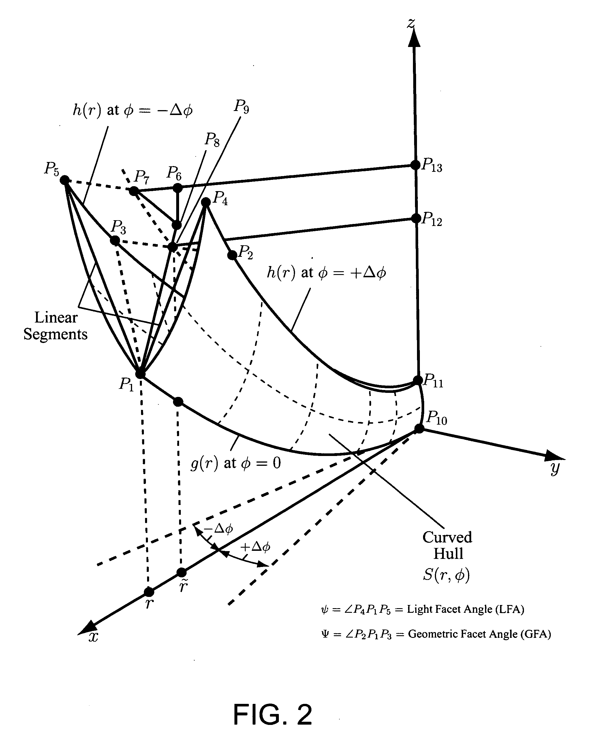
The eleventh disadvantage of the prior art is that when curved facets are employed they tend to be small structures relative to the size of the largest dimension of the device and to incorporate very acute angles at their apex thereby making them difficult to manufacture and fragile.
The twelfth disadvantage is that the prior art can not provide both concentrated light and dispersed light to both a high efficiency photovoltaic cell that uses only directly concentrated light and to thin-film photovoltaic cells for dispersed light simultaneously.
While all of these disadvantages may not exist for any one particular prior art design all of the previously mentioned sources of prior art do suffer from one or more of the above stated deficits.
“Protected Total Internal Reflection (PTIR)” as used herein refers to an optical surface that provides Total Internal Reflection and is shielded from environmental elements like dirt or aerosols, which would adhere to said optical surface and reduce the efficiency of the Total Internal Reflection process.
“Unprotected Total Internal Reflection (UTIR)” as used herein refers to an optical surface that provides Total Internal Reflection and is not shielded from environmental elements like dirt or aerosols, which would adhere to said optical surface and reduce the efficiency of the Total Internal Reflection process.
Unfortunately, this last equation is not a closed analytical relation because it requires that Eq.
Note that the greater the refractive index ninside relative to noutside the larger the acceptance angle of a cone of light rays and also the larger the potential final concentration of light, however, the greater the mismatch in refractive indices between the surrounding air and the lens—this may increase reflection losses.noutside—Typically air.
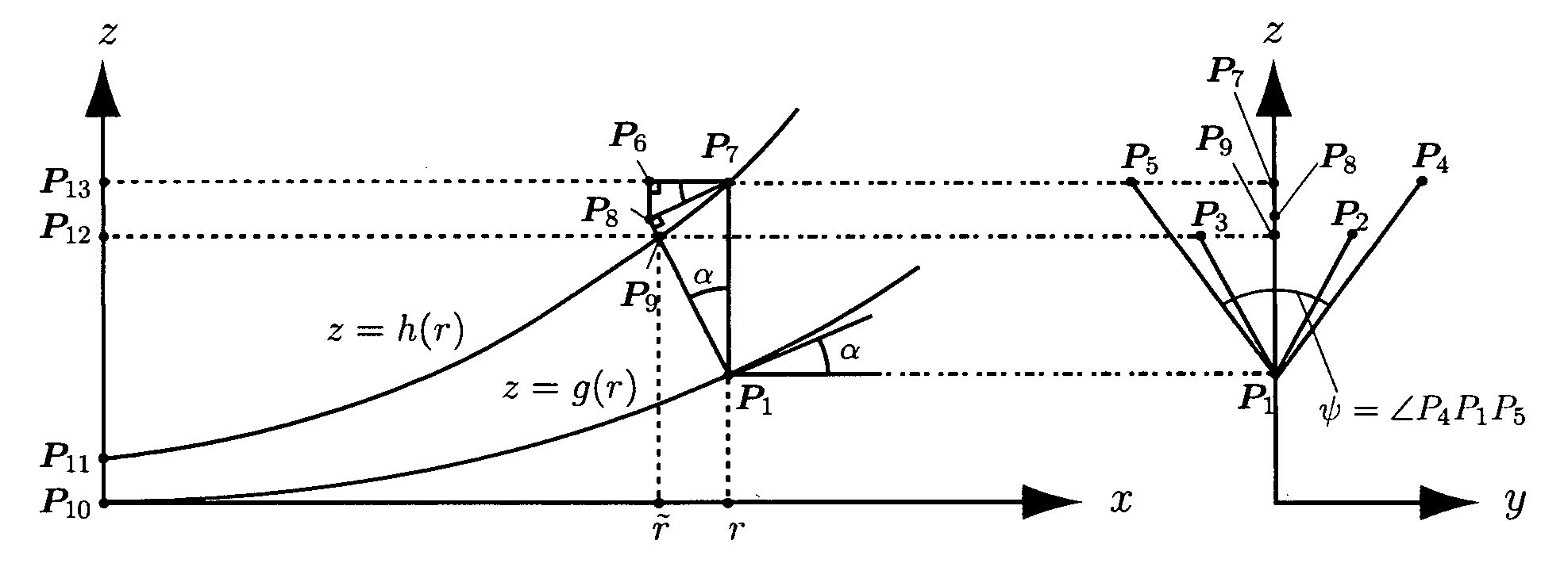
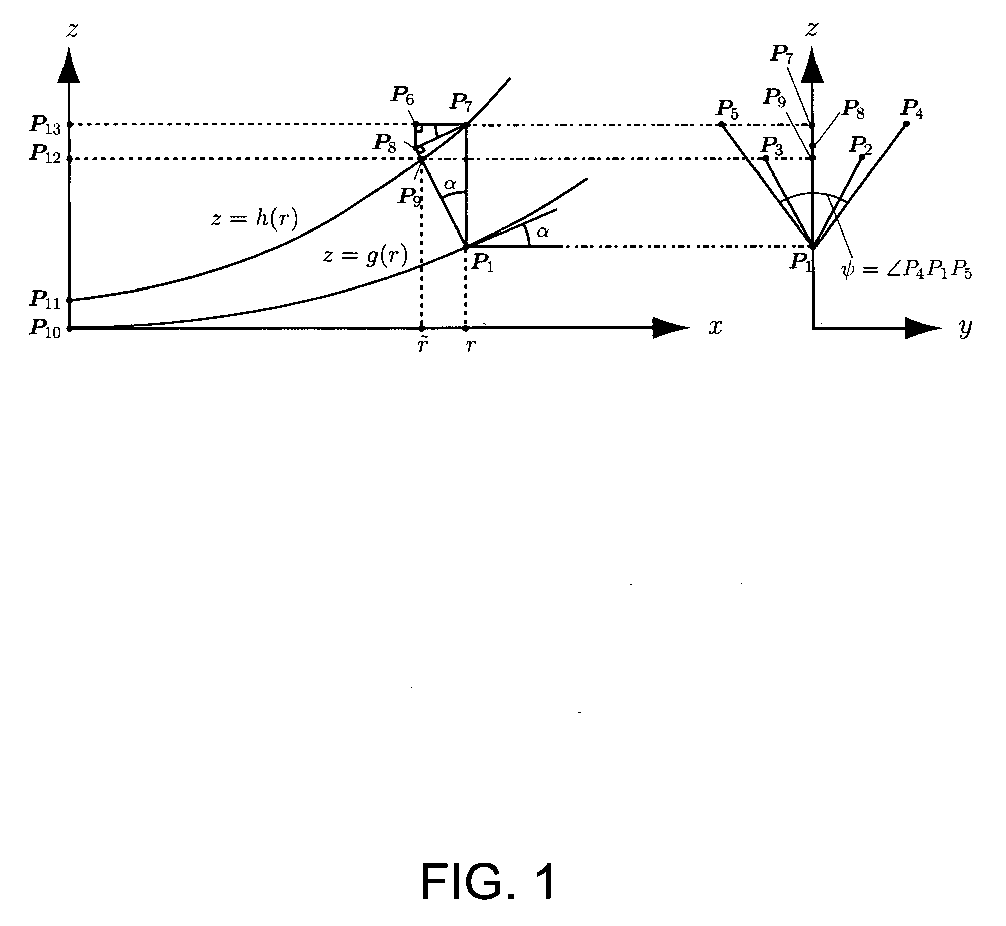
Note that the linear facet control plane is the most rudimentary facet structure possible and in general will have associated with it many problems that need correction.

Method used


Image

  • Non-imaging facet based optics
  • Non-imaging facet based optics
  • Non-imaging facet based optics

Examples


Embodiment Construction

[0146]FIG. 3 shows a facet subcomponent of a concentrator. It is a single facet that transforms an input light-cone forming the input edge-rays 300, having an input angle 305 of angular extent 2θin, to an output light-cone forming output edge-rays 335, having an output angle 340 of angular extent 2θout. This single facet concentrator comprises a transparent top input surface 330 and a bottom transparent facet surface 360. These surfaces are part of a contiguous homogenous and transparent facet 3 having an dielectric index of refraction nd that is greater than the surrounding medium na, which is typically air. The input edge rays pass through the input aperture at the light-cone-apex 315 and emerge at the output aperture 345, which is symmetrically positioned about the optical axis 350. The pattern of light made by the input edge rays 300 is typically, but limited to, a conic section for a simple and well designed facet surface 360. The light-cone is redirected by TIR at a first face...


PUM


Abstract

A high efficiency and compact optical device comprising two or more active and resonating optical facet surfaces defined by a three-dimensional representation and configured to provide a three-dimensional device. A focal region, remote from the optical surfaces and non-contiguous therewith, is defined by two or more active optical resonant surfaces, at least one of which is self-resonant. The optical surfaces in general do not have a continuous second derivative and are defined by a piecewise continuous surface function providing radially directed facets. The optical device comprises a transparent dielectric body with its optical surfaces being formed on the surfaces of said transparent dielectric body. A light transducer may be located at a focal region to provide an energy conversion. A light source having a physical extension in space, such as an LED, may be located at the focal region to provide collimation. In some embodiments the active surfaces may be chosen to transform incident radiation into a predetermined shape and having a predetermined spatial power distribution.

Description

CROSS-REFERENCE TO RELATED APPLICATIONS [0001]This invention claims the benefit of U.S. provisional patent application: U.S. 60 / 879,657 filed by the inventor, Leo D. DiDomenico, on Jan. 10, 2007 and entitled “Non-Imaging Faceted Light Concentrator”. U.S. provisional patent application 60 / 879,657 is hereby incorporated in the present disclosure in its entirety and for all purposes in this patent disclosure.FEDERALLY SPONSORED RESEARCH[0002]Not ApplicableSEQUENCE LISTING OR PROGRAM[0003]Not ApplicableBACKGROUND OF THE INVENTION [0004]1. Field of Invention[0005]This invention relates to facet-based, compact, and high-efficiency optical concentrators, collimators, reflectors, and couplers that do not, in general, preserve the point-to-point ordering of the input light rays so that maximum power transfer from a first aperture to a second aperture is achieved.[0006]2. Prior Art[0007]The physical processes that are available to the designer of a light concentrator are limited. Following wh...

Claims


Application Information

Patent Timeline
Patent Type & Authority Applications(United States)
IPC IPC(8): G02B17/00F21V5/00F24S23/00F24S23/70
CPCF24J2/062F24J2/085G02B5/045G02B27/095G02B19/0033Y02E10/43G02B19/0042G02B19/0028G02B27/0977F24S23/10F24S23/31Y02E10/40
Inventor DIDOMENICO, LEO DAVID
Owner WEISS COREY A
Why Eureka
Try Eureka