
Loudspeaker protection circuit

a protection circuit and loudspeaker technology, applied in the direction of transducer protection circuits, limiting amplitudes, electrical devices, etc., can solve the problems of inability to adequately protect the transducer, the attenuation plateau of the lamp, and the significantly less of the lamp, so as to increase the control of the rms, protect the lamp filament from over-power conditions, and reduce the effect of nois

Active Publication Date: 2008-07-10
DOLBY LAB LICENSING CORP
View PDF9 Cites 11 Cited by
  • Summary
  • Abstract
  • Description
  • Claims
  • Application Information

AI Technical Summary

Benefits of technology

[0013]The present invention overcomes the above-identified as well as other problems and disadvantages in the art of loudspeaker protection by providing a protection circuit operable to provide fully adjustable dynamic attack timing & threshold / s, minimized insertion loss, gradual dynamic attenuation, high speed peak over-voltage protection, wide operational power range, full-bandwidth operation, and anti-chatter hysteresis. Though not limited thereto, this protection circuit, when configured in multiple stages, is ideal for sensitive loudspeaker devices that require average and peak power limiting. It should also be noted that the present invention derives all necessary operational power from the audio signal driving the loudspeaker and does not require a secondary power source. This is ideal for passive loudspeakers wherein no secondary power supply is available.
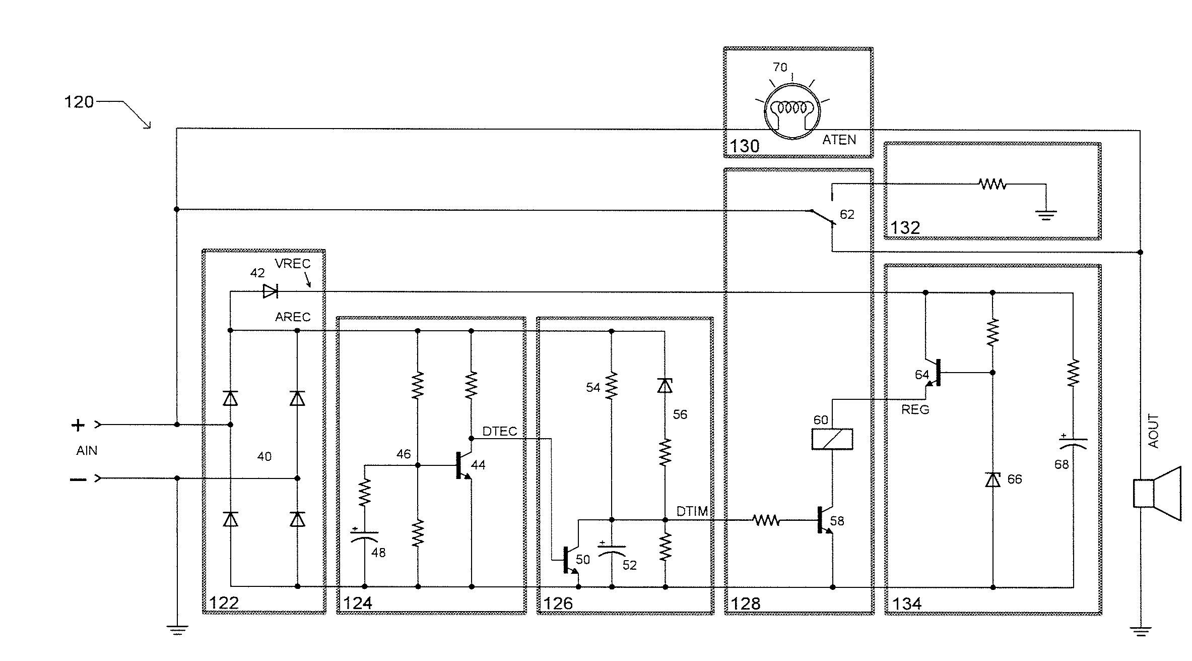
[0016]The timing stage is operable to receive the detection stage output signal, DTEC, and derive therefrom a time delayed output signal, DTIM. If the detection stage output signal, DTEC, goes inactive during the timing period leading up to DTIM activation, the timing stage may be designed to clear the timer and await the next trigger from DTEC. The timing stage may also be designed to receive the rectified audio signal, AREC, and derive therefrom a dynamically adjustable expiration time. The purpose of the timing stage is to provide a controlled attack time allowing brief DTEC triggers to pass without activating DTIM; however, activating DTIM when DTEC has remained active over the timer expiration period. Dynamically adjusting the timer expiration period based upon the rectified audio signal, AREC, is advantageous because loudspeaker power handling varies depending upon the duration of the applied signal. Though not limited thereto, the timing stage may contain multiple timing stages allowing multiple expiration times for various rectified audio, AREC, input signals.
[0018]The actuation stage is operable to receive the timing stage output signal, DTIM, the regulation stage output, REG, and the audio input signal, AIN, and therefrom adequately control an actuator device. Selection of the actuator device depends upon the application and the desired connection to the attenuation stage and / or the optional load balancing stage. Though not limited thereto, the preferred actuator is a single-pole, double-throw relay with the pole connected to the audio input, AIN, the normally-closed contact connected to the audio output, AOUT, and the normally-open contact connected to an optional load balancing stage. An optional hysteresis technique can be implemented within the actuation stage to eliminate actuator chatter.
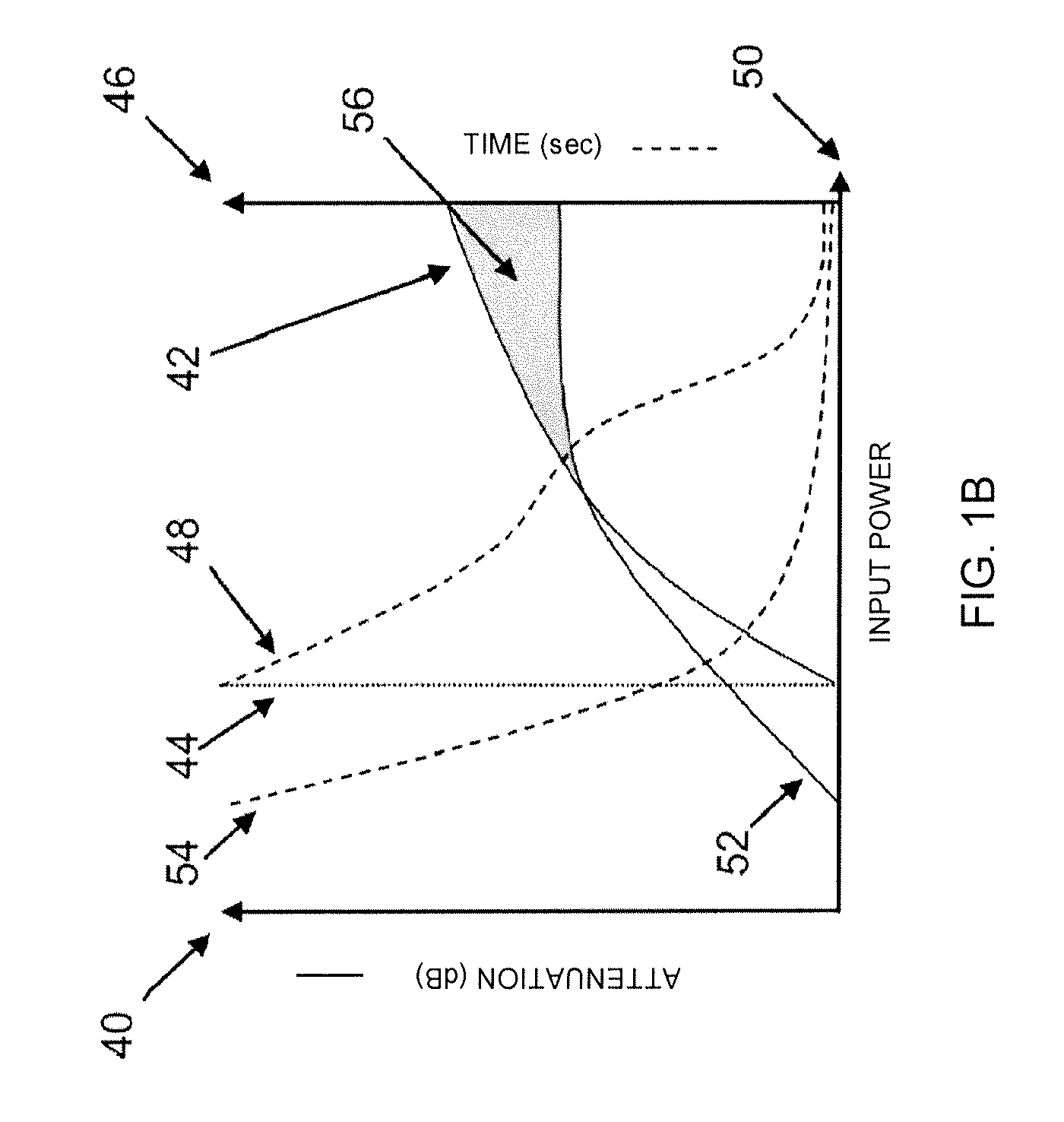
[0021]Though not limited thereto, it's often desirable to incorporate multiple stages of the present invention to allow for increased control of RMS and peak limiting. The preferred method of implementing a multi-stage protection circuit is to incorporate N number of detection, timing, actuation, and attenuation stages, while utilizing a common rectification stage, regulation stage, and optional load balancing stage. This technique, in conjunction with the selection of lamp attenuation stages, allows gradual linear attenuation but solves the typical lamp problem of insufficient attenuation at higher power levels and inherently protects the lamp filament from over-power conditions. Such a technique also allows the designer to more closely match the required attenuation performance of the loudspeaker.

Problems solved by technology

Unfortunately, these attempts have failed to adequately protect the transducer while allowing all permissible voltages and currents to pass unaltered.
Unfortunately, self-actuating devices are not adjustable and actuation threshold can vary significantly depending on ambient temperature and / or production tolerances.
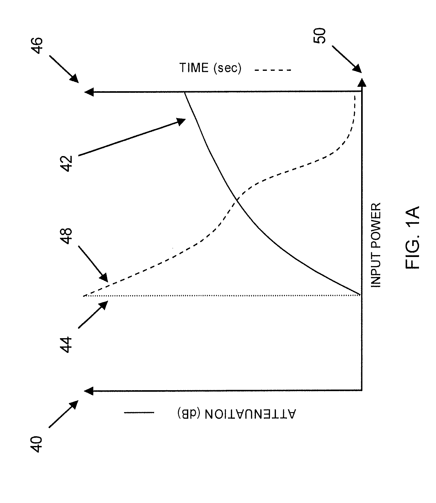
Unfortunately, the lamps attenuation plateaus and is significantly less than what the loudspeaker requires to maintain damage-free operation.
Unfortunately, the lamp's excessive speed will clamp transient power levels quicker than required resulting in a less-musical solution.
Lamps also have a nominal impedance even when they are not actuated or lighting, which results in a measurable insertion loss.
Additionally, lamps have a maximum power rating and the filament can be damaged upon over-powering the device, which greatly limits the operational power range of circuits that incorporate lamps without subsequent filament protection.
While the PTC does offer adequate attenuation, the fast-acting step attenuation response is not musical and easily detected by the human ear.
Unfortunately, while selecting smaller PTC devices will speed the time response, the actuation threshold is typically much less than the desired power rating of the loudspeaker.
Additionally, PTC devices will remain actuated with a small amount of trickle current, leading to poor release and recovery performance.
PTC actuation thresholds will also vary greatly depending upon the ambient temperature, greatly limiting the effective operational temperature range of circuits incorporating such devices.
Because of these problems, designers have great difficulty finding a single PTC device that meets all of the desired requirements with respect to time, attenuation, actuation thresholds, and release performance.
Unfortunately, the inadequate attenuation of the lamp at higher power levels remains a problem and allows operation in the damage region, 56.
Replacing the lamp attenuator with a constant impedance attenuator results is a large stepped attenuation, which is not musical and easily detected by the human ear.
Unfortunately, the excessive speed will clamp transient power levels quicker than required, again making the protection topology less musical.
Additionally, typical relay designs have suffered from actuation chatter wherein the relay actuates and releases rapidly when the input signal is crossing the relay coil threshold.
Such chatter degrades the life of the relay contacts significantly.
Existing designs that incorporate thyristors or clamping diodes are effective in limiting peak voltages; however, excessive currents exist when clamping and can result in damage to the clamping device, the driving amplifier, or the passive crossover connected thereto.
Such crow-bar, clamping techniques result in non-linear loading on the driving device and are not acceptable for protection circuits that are required to connect to a variety of different amplifiers and / or required to connect to the output of a passive crossover filter requiring proper termination.
In summary, existing protection circuits have suffered from the following problems: uncontrolled response time (excessively fast or slow), high insertion loss, frequency selectivity, abrupt stepped actuation, non-linear loading, inadequate peak voltage and current protection, limited operational power range, and actuation chatter.

Method used


Image

  • Loudspeaker protection circuit
  • Loudspeaker protection circuit
  • Loudspeaker protection circuit

Examples


first embodiment

[0041]Referring to FIG. 2A, a protection circuit 20 is shown constructed in accordance with a preferred first embodiment of the present invention. The protection circuit 20 is operable to provide fully adjustable dynamic attack timing & threshold, minimized insertion loss, gradual dynamic attenuation, high speed peak over-voltage protection, wide operational power range, optional load balancing and full-bandwidth operation through the use of a voltage detector, a timer, actuator, attenuator, regulator, and optional load balancer. The preferred loudspeaker protection circuit broadly comprises a rectification stage 22; a detection stage 24; a timing stage 26; an actuator stage 28; an attenuation stage 30; a regulation stage 34; and an optional load balancing stage 32.

embodiment 120

[0042]The rectification stage 22 is operable to derive two rectified signals, AREC and VREC, and broadly comprises a first rectifier circuit 40 followed by a subsequent second rectifier 42. The subsequent second rectifier 42 may be connected to the output of the said first rectifier 40, referred to as AREC, and is used to create a second rectified signal VREC. The first rectified signal, AREC, is supplied to the detection stage, 24, and the timing stage, 26. These subsequent stages are designed with relatively low capacitance, thereby maintaining AREC as a time-varying, rectified audio signal. Output of second rectifier 42, VREC, is supplied to the regulation stage 34 which includes smoothing capacitance, thereby ensuring that VREC is a time-averaged voltage. Referring to FIG. 2B, a detailed example of the first-embodiment 120, illustrates one possible implementation of the rectification stage wherein the first rectifier circuit 40 is constructed as a full-bridge rectifier utilizing...

second embodiment

[0050]Referring to FIG. 3A, a protection circuit 220 is shown constructed in accordance with a preferred second embodiment of the present invention. The protection circuit 220 is operable to provide multiple stages of fully adjustable dynamic attack timing & thresholds, minimized insertion loss, multiple stages of gradual dynamic attenuation, high speed peak over-voltage protection, wide operational power range, optional load balancing and full-bandwidth operation through the use of multiple voltage detectors, multiple timers, multiple actuators, multiple attenuators, regulator, and optional load balancer. The second preferred loudspeaker protection circuit broadly comprises the same stages as discussed in regards to the first preferred embodiment; however, includes a plurality of detection stages 224&240, timing stages 226&238, actuation stages 228&236, and attenuation stages 230&242. The purpose of adding multiple detectors, timers, actuators, and attenuators is to allow attenuati...


PUM


Abstract

A loudspeaker protection circuit comprises a rectification stage for receiving an input audio signal and producing a rectified output signal, a detection stage for passing the rectified output signal when the rectified output signal is greater than a predetermined level, a timing stage for receiving the rectified output signal from the detection stage and producing a time-varying charge signal, a regulation stage for producing a regulated output signal based on the input audio signal, an actuator stage for actuating a switch based on the time-varying charge signal and the regulated output signal, and an attenuation stage for attenuating an output audio signal when the switch is actuated.

Description

RELATED APPLICATIONS[0001]The present application claims priority benefit to U.S. provisional patent application entitled “LOUDSPEAKER PROTECTION CIRCUIT”, Ser. No. 60 / 884,167, filed Jan. 9, 2007. This provisional application is incorporated into the present application by reference.BACKGROUND OF THE INVENTION[0002]1. Field of the Invention[0003]Embodiments of the present invention relate to loudspeaker protection circuitry. More particularly, embodiments of the present invention relate to a low-cost, sonically transparent, multi-stage loudspeaker protection circuit that protects a loudspeaker device from RMS and short-duration transient over-voltage conditions while accommodating adjustable threshold and dynamic attack timing.[0004]2. Description of the Related Art[0005]It is often desirable to protect a loudspeaker from excessive voltage and current conditions which may lead to permanent damage to the loudspeaker. It is also desirable to allow permissible voltages and currents to ...

Claims


Application Information

Patent Timeline
IPC IPC(8): H03G11/00
CPCH04R3/007
Inventor BUTLER, JOEL
Owner DOLBY LAB LICENSING CORP
Learn More