Closed System and Method for Atraumatic, Low Pressure, Continuous Harvesting, Processing, and Grafting of Lipoaspirate

a closed system and liposuction technology, applied in the field of closed system and method for liposuction, can solve the problems of high pressure, impracticality and unreliability, and excessive process, and achieve the effects of reducing the efficiency of liposuction, reducing excess body contour, and improving the survival of fat grafts

Active Publication Date: 2008-07-10
LIPOCOSM LLC
View PDF19 Cites 85 Cited by
  • Summary
  • Abstract
  • Description
  • Claims
  • Application Information

AI Technical Summary

Benefits of technology

[0003]The process of liposuction, or the harvest of subcutaneous fat, is commonly performed with a lipoaspirator machine that generates about one atmosphere vacuum pressure and has a collection flask connected in series between the suction cannula and the vacuum pump. It is well accepted that one atmosphere vacuum pressure is most effective if the intent is to simply remove and discard the fat to reduce excesses in body contour. However, if the intent is to reinject this aspirated tissue as a graft, one atmosphere pressure is too high as it inflicts significant damage to the adipocytes sufficient to render them undesirable for reinjection. Therefore, for the purpose of re-grafting or reinjection it is generally known that lower vacuum pressures, closer to one half

Problems solved by technology

The autologous grafting of liposuctioned tissue holds much promise in plastic surgery; but being very technique dependent, and lacking a simple apparatus to perform it, it has a reputation for being impractical and unreliable.
The process becomes extremely arduous and time consuming when large volumes a

Method used


Image

  • Closed System and Method for Atraumatic, Low Pressure, Continuous Harvesting, Processing, and Grafting of Lipoaspirate
  • Closed System and Method for Atraumatic, Low Pressure, Continuous Harvesting, Processing, and Grafting of Lipoaspirate
  • Closed System and Method for Atraumatic, Low Pressure, Continuous Harvesting, Processing, and Grafting of Lipoaspirate

Examples


Embodiment Construction

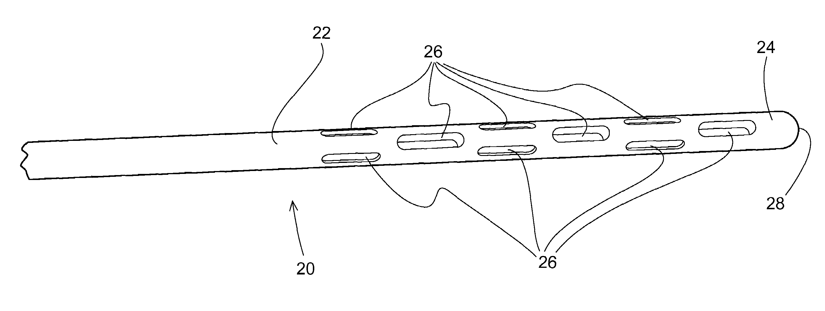
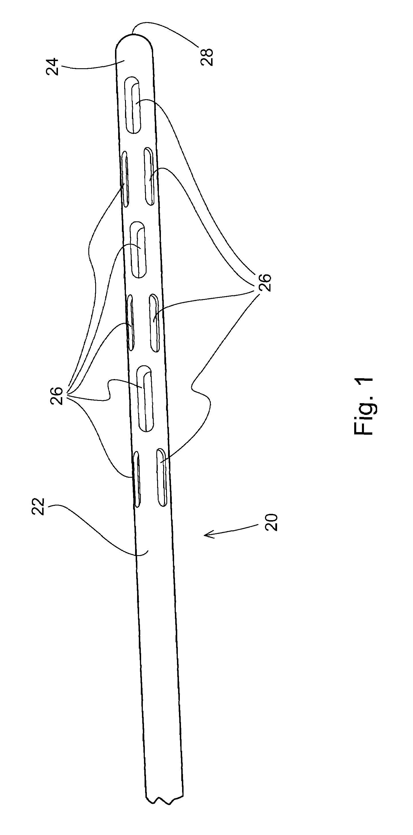
[0018]As has become known in the art, grafted fat globules have to first survive by diffusion and what is called plasmatic imbibition until they get revascularized from the recipient bed. Larger globules that have a lower surface to volume ratio cannot get enough nutrients to survive and therefore die off before getting revascularized. This improved understanding of the physiology of graft survival led to the use of smaller bore cannulas with smaller openings that harvest smaller globules of fat. While generally speaking the smaller the better, very small is impractical in terms of harvesting efficiency, especially when large volumes are required for the particular procedure. It is well recognized today that the ideal harvesting cannulas should have diameters between 2-3 mm and harvesting slits (hole openings) between 0.5 and 3 mm.

[0019]The most commonly used and commercially available cannulas for liposuction are either blunt ended with a single side hole, three side holes (Mercede...


PUM

PropertyMeasurementUnit
Lengthaaaaaaaaaa
Lengthaaaaaaaaaa
Lengthaaaaaaaaaa

Abstract

A closed system for harvesting fat through liposuction, concentrating the aspirate so obtained, and then re-injecting the concentrated fat into a patient comprises as its main components a low pressure cannula having between about 7 to 12 side holes of about 1-2 mm by 2.0 to 4.0 mm, a spring loaded syringe holder with a helicoidal spring to apply a substantially constant pressure over the full excursion of the plunger, and a preferably flexible collection bag which is also preferably graduated, cylindrical over most of its body and funnel shaped at its bottom, all of which are connected through flexible tubings to a multi-port valve. The multi-port valve has two flutter/duck bill valves which restrict the fluid flow to a one way direction which effectively allows the syringe to be used to pump fat out of a patient and into a collection bag in a continuous manner. After the bags are centrifuged to concentrate the fat, the excess fluids are separated and the valve is re-connected to permit the syringe pump to reverse fluid flow to graft the concentrated fat back into the patient.

Description

CROSS REFERENCE TO RELATED APPLICATION[0001]Priority is claimed to provisional U.S. Patent Application Ser. No. 60 / 828,505 filed Oct. 6, 2006 entitled Method and Apparatus for Lipotransfer, the disclosure of which is incorporated herein by reference.BACKGROUND AND SUMMARY OF THE INVENTION[0002]The autologous grafting of liposuctioned tissue holds much promise in plastic surgery; but being very technique dependent, and lacking a simple apparatus to perform it, it has a reputation for being impractical and unreliable. Generally, as presently performed in the prior art, the process requires harvesting with suction cannulas delicate and finicky adipocytes, separating them, concentrating them, and then re-grafting them a droplet at a time into a three-dimensional recipient matrix in aliquots small enough to survive through diffusion yet separated enough to avoid crowding. The process becomes extremely arduous and time consuming when large volumes are involved. One of the inventors herein...

Claims


Application Information

Patent Timeline
IPC IPC(8): A61M1/00A61M5/00A61M39/22
CPCA61M1/0009A61M1/008A61M2202/08A61M5/1452A61M39/24A61M5/14216A61M2202/0021A61M2205/073Y10T137/7838Y10T137/87249A61M1/67A61M1/84A61M1/71A61M1/81A61M1/895A61M1/892A61M1/87
Inventor KHOURI, ROGER K.KURU, MURAT
Owner LIPOCOSM LLC
Why Eureka
Try Eureka