
Motor controller and electric power steering system

a technology of motor controller and electric steering system, which is applied in the direction of non-deflectable wheel steering, angular speed control of ac motors, underwater vessels, etc., can solve the problems of motor compensation, worse than torque ripple, and torque ripple, and achieve the effect of reducing the torque rippl

Inactive Publication Date: 2008-07-10
JTEKT CORP
View PDF3 Cites 41 Cited by
  • Summary
  • Abstract
  • Description
  • Claims
  • Application Information

AI Technical Summary

Benefits of technology

[0008]The present invention has been conceived to solve the above-mentioned problem and aims at providing a motor controller and an electric power steering system which can reduce a torque ripple.
[0020]As a result, when the rotational speed of the motor is not equal to or greater than the first threshold value, the controller controls the motor in accordance with the predetermined target current command value corrected by the correction unit, thereby reducing the torque ripple in the motor. In the meantime, when the rotational speed of the motor becomes equal to or greater than the first threshold value, the compensating current command value comes to zero, so that the torque ripple is not compensated for. Consequently, when the rotational speed of the motor is equal to or greater than the first threshold value, the compensated torque ripple does not become worse than the uncompensated torque ripple, and at least the uncompensated torque ripple is maintained, so that the torque ripple can be reduced.
[0022]Even when the rotational speed of the motor is not equal to or greater than the first threshold value, the compensating current command value can be computed appropriately by setting the second threshold value in accordance with steering conditions. Consequently, even when the rotational speed of the motor is not equal to or greater than the first threshold value, the torque ripple can be reduced.
[0023]In the third aspect of the invention, the motor controller defined in the first and second aspects causes the motor to generate steering assist force in response to steering operation, thereby assisting steering operation. As a result, there can be implemented an electric power steering system which exhibits the working-effects yielded by the invention defined in the first and second aspects, such as an effect of the compensating current command value coming to zero when the rotational speed of the motor is increased to the first threshold value or more, so that a compensated torque ripple does not become worse than an uncompensated torque ripple, and the like. Therefore, there can be provided an electric power steering system is capable of reducing a torque ripple even when the rotational speed of the motor is increased.

Problems solved by technology

Moreover, when the rotational speed of the motor increases further, it may be the case where the torque ripple (a torque ripple achieved after compensation) of the motor compensated for in accordance with the compensating current computed by the torque ripple compensation section will become worse than the torque ripple acquired before compensation.

Method used


Image

  • Motor controller and electric power steering system
  • Motor controller and electric power steering system
  • Motor controller and electric power steering system

Examples


Embodiment Construction

[0079]An embodiment of the present invention will be described hereunder by reference to the accompanying drawings.

[0080]

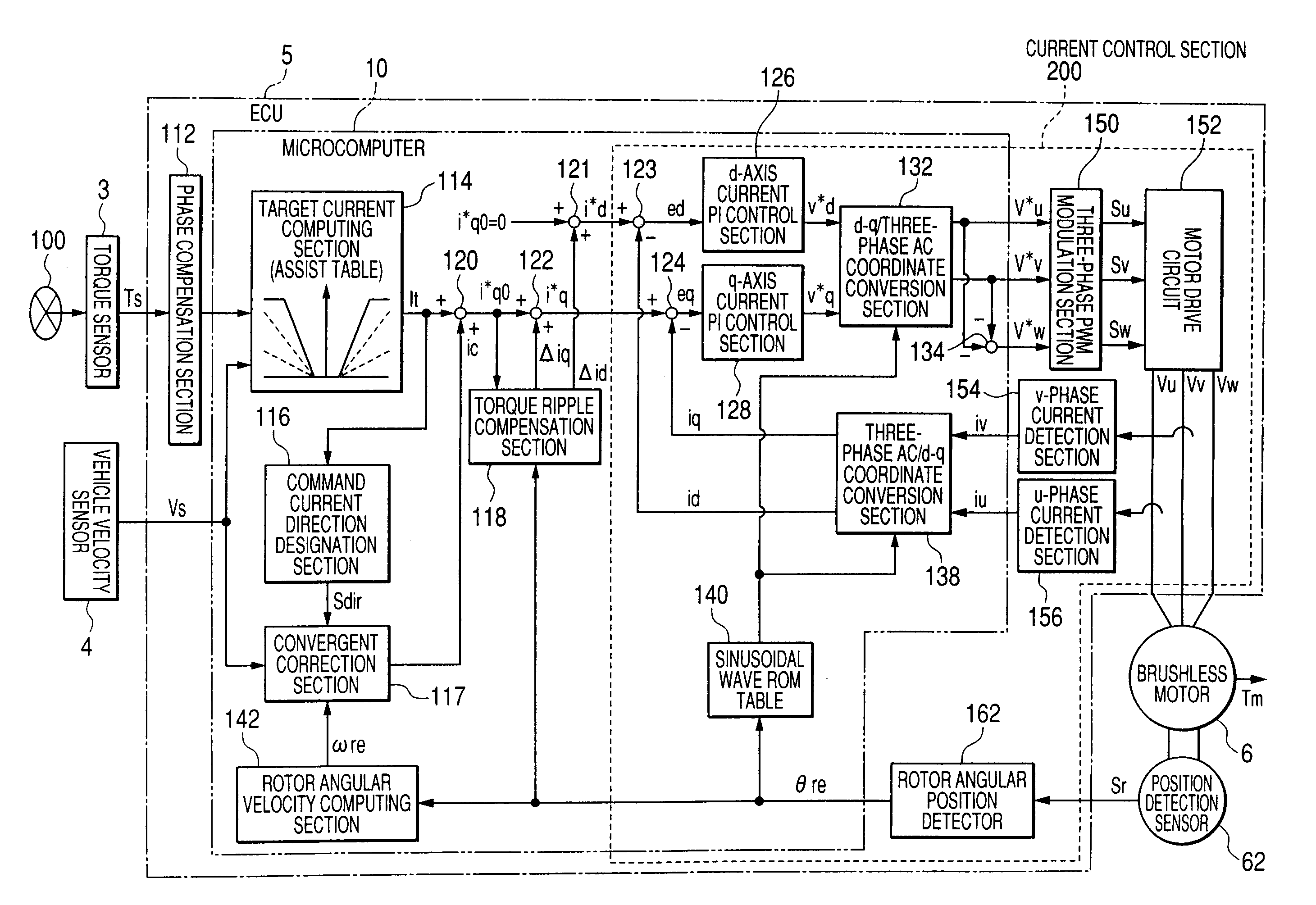
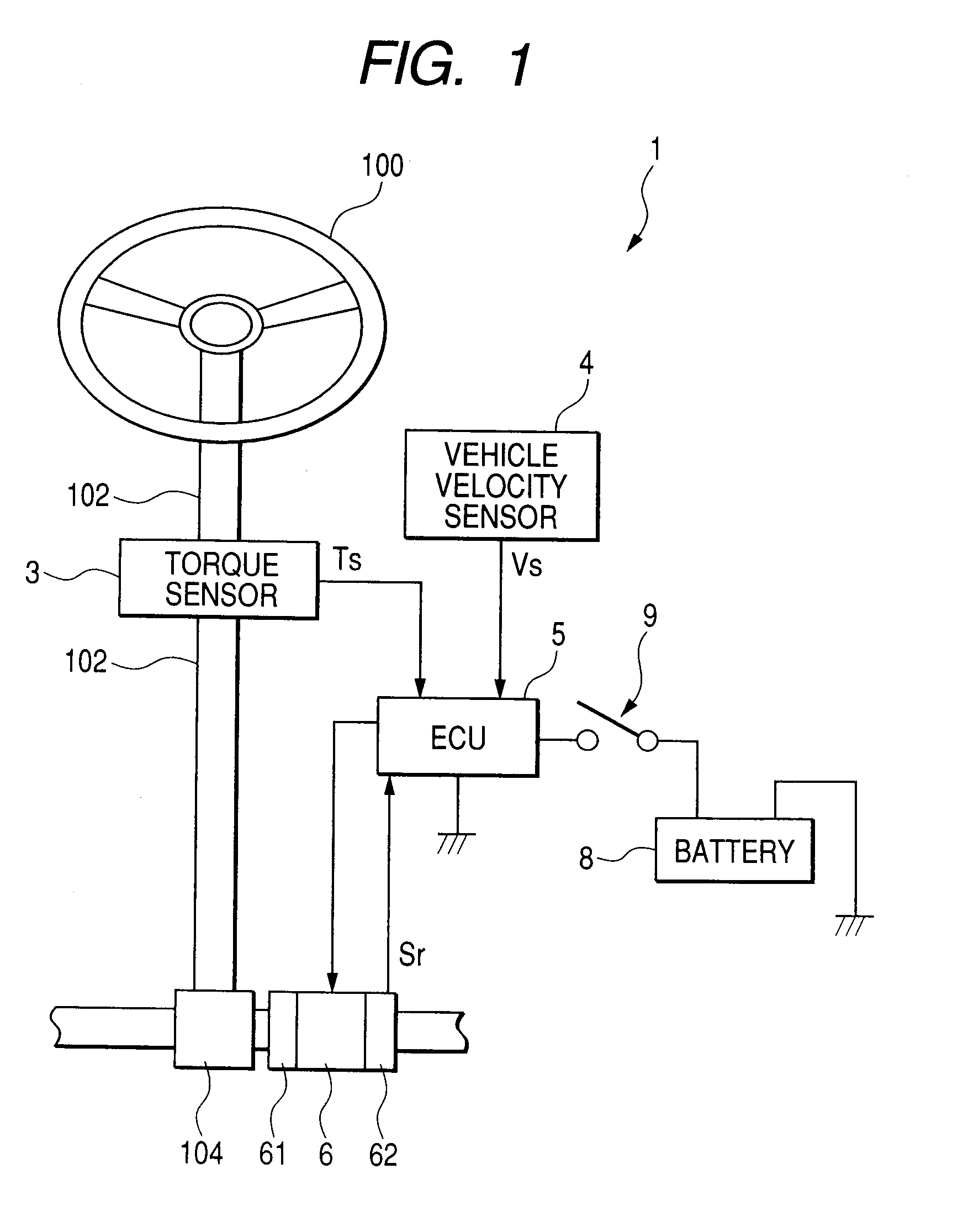
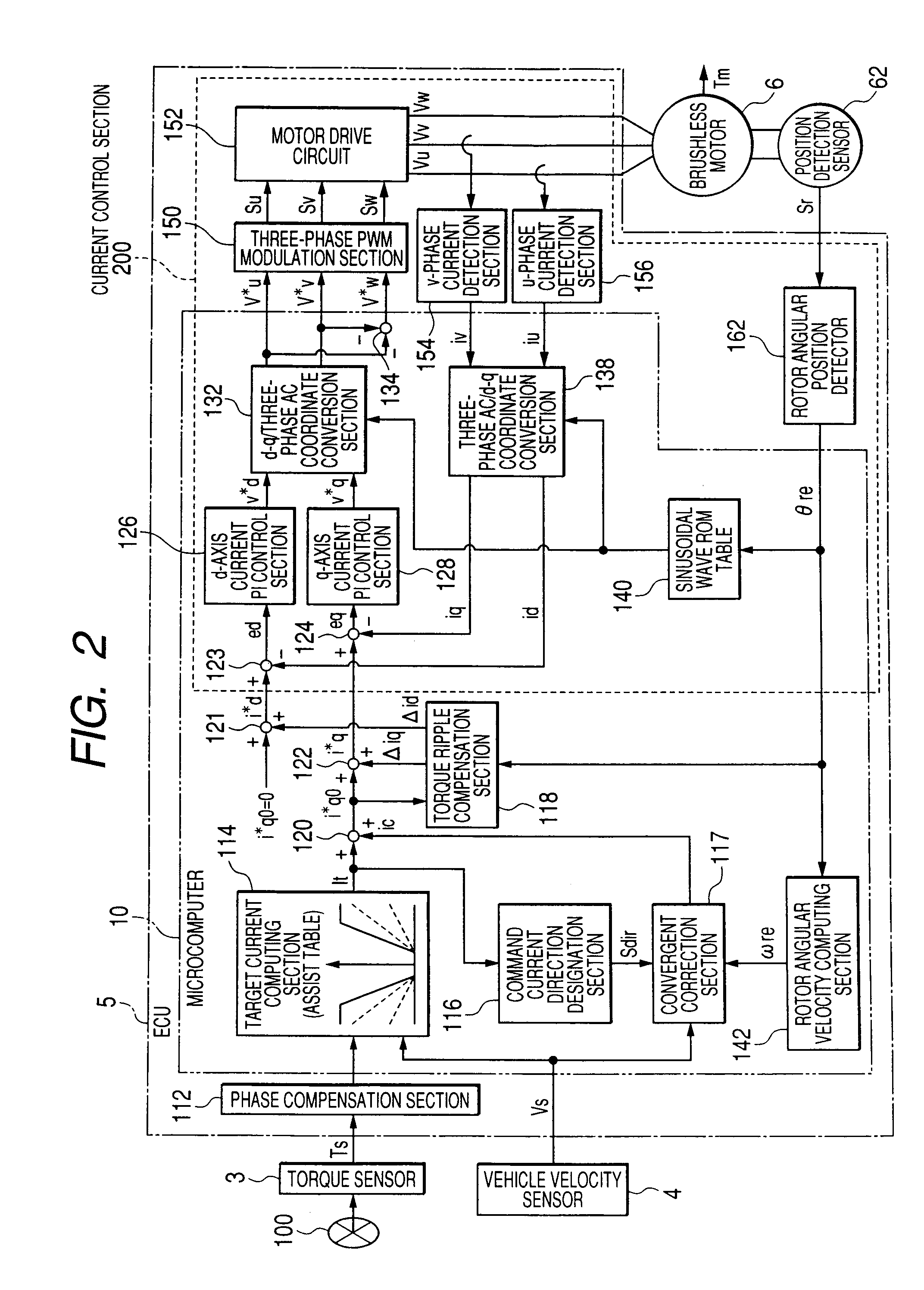
[0081]FIG. 1 is a schematic diagram showing the configuration of an electric power steering system 1 of an embodiment of the present invention in conjunction with the configuration of a vehicle related to the system. The electric power steering system 1 has a steering shaft 102 fixed at its one end to a handle (a steering wheel) 100 serving as an operation unit for steering purpose; a rack-and-pinion mechanism 104 joined to the other end of the steering shaft 102; a torque sensor 3 for detecting steering torque applied to the steering shaft 102 by operation of the handle 100; a brushless motor 6 which generates steering-assist force for lessening a burden imposed on a driver during handle operation (steering operation); a ball screw drive section 61 for transmitting the steering-assist force to a rack shaft; a position detection sensor 62, such as a resolver, for ...


PUM


Abstract

In a case where a computing period of a torque ripple compensation section which computes current compensation values Δid and Δiq to be caused to flow into a motor in order to prevent occurrence of a torque ripple in the motor differs from a control period of a current control section which controls a feedback to the motor in such a way that current command values i*d and i*q additionally provided with the current compensation values Δid and Δiq flow into the motor, the microcomputer sets the current compensation values Δid and Δiq to zero when a rotor angular velocity ωre of the motor is equal to or greater than a first threshold value ω1.

Description

[0001]This application is based upon and claims the benefit of priority of Japanese Patent Application No. 2007-001376 filed on Jan. 9, 2007, the contents of which are incorporated herein by reference in its entirety.BACKGROUND OF THE INVENTION[0002]The present invention relates to a motor controller and an electric power steering system.[0003]An electric power steering system described in, for example, JP-A-2004-328814 has hitherto been known as a system for reducing a torque ripple in a motor which assists steering operation performed by a steering wheel of a vehicle. The electric power steering system changes a compensating current computed by a toque ripple compensation section so as to prevent occurrence of a torque ripple in a motor in accordance with the rotational speed of the motor as well as in accordance with a load imposed on the motor. As a result, a current control section provides the motor with an appropriate compensating current even in a case where the rotational s...

Claims


Application Information

Patent Timeline
IPC IPC(8): B62D5/04H02P6/06H02P6/10H02P6/08H02P21/00H02P21/05H02P21/22H02P23/04H02P23/16H02P23/18H02P27/04
CPCB62D5/046H02P21/0003H02P29/0038H02P21/05H02P21/04H02P29/50
Inventor SUZUKI, HIROSHI
Owner JTEKT CORP
Learn More