Method and Apparatus for Enhancing the Efficiency of Operation of an Internal Combustion Engine

a technology of internal combustion engine and efficiency enhancement, which is applied in the direction of combustion engine, internal combustion piston engine, machine/engine, etc., can solve the problems of reducing the control of engine power output, affecting reducing the efficiency of internal combustion engine, so as to enhance the timely delivery of multiple flame fronts, enhance the power delivered by the engine and acceptable exhaust emissions, and enhance the fuel consumption efficiency of an ice

a technology of internal combustion engine and efficiency enhancement, which is applied in the direction of combustion engine, internal combustion piston engine, machine/engine, etc., can solve the problems of reducing the control of engine power output, affecting reducing the efficiency of internal combustion engine, so as to enhance the timely delivery of multiple flame fronts, enhance the power delivered by the engine and acceptable exhaust emissions, and enhance the fuel consumption efficiency of an ice

US20080168963A1Inactive Publication Date: 2008-07-17ECONO PLUG TECH

Image

  • Method and Apparatus for Enhancing the Efficiency of Operation of an Internal Combustion Engine
  • Method and Apparatus for Enhancing the Efficiency of Operation of an Internal Combustion Engine
  • Method and Apparatus for Enhancing the Efficiency of Operation of an Internal Combustion Engine

Examples


Embodiment Construction

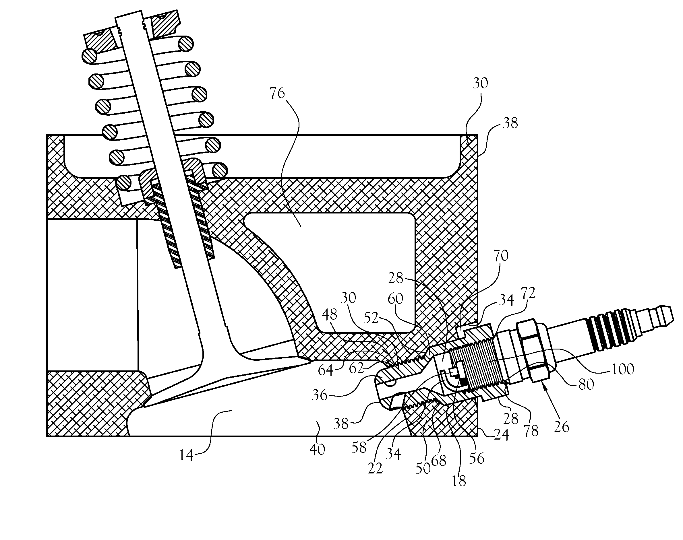
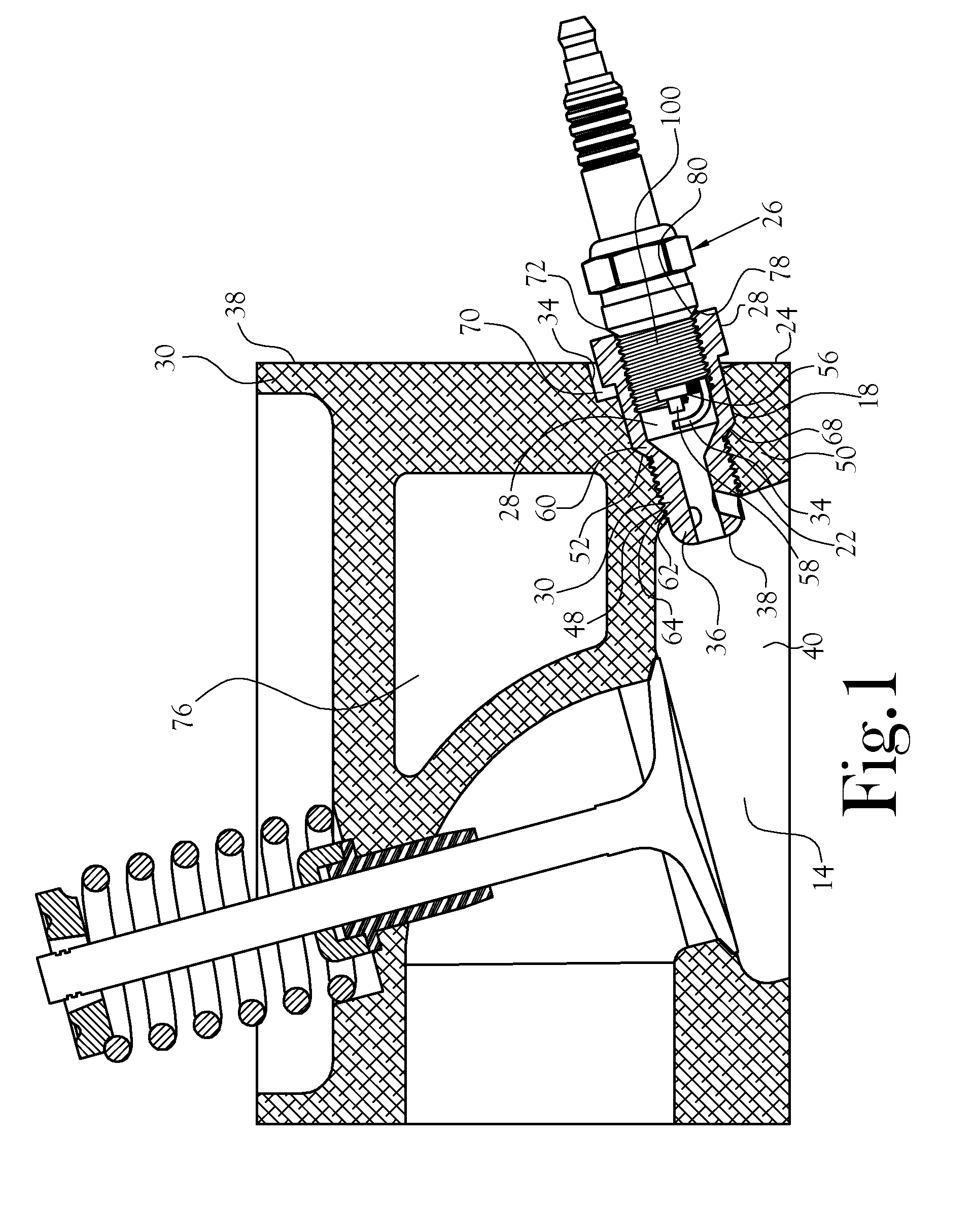
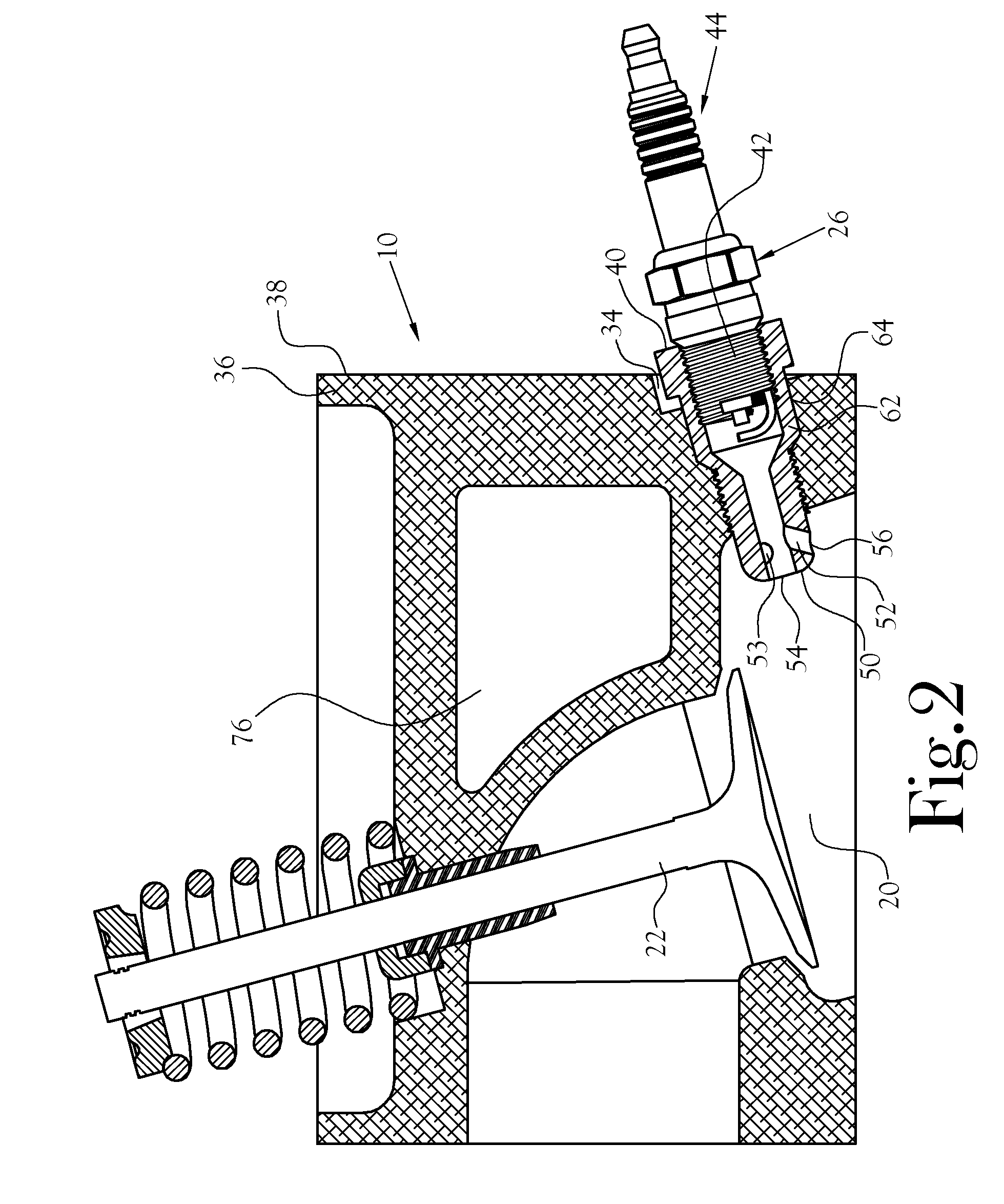
[0032]The present invention relates to an ICE. Referring to FIGS. 1 and 12, a conventional ICE 10 includes a piston 12 reciprocatably mounted within a cylinder 14. A connecting rod connects the piston with a crankshaft whose rotation transfers power to the drive train of a motor vehicle. Referring to FIG. 1, the cylinder opens into a combustion chamber 20 within which a fuel / air mixture (at times “F / A”) is ignited by a spark plug 44 and burned to develop pressure and heat effective to drive the piston within its cylinder, hence effect rotation of the crankshaft. Within the combustion chamber there is included an intake valve 22 through which “fresh” F / A is admitted to the combustion chamber and an exhaust valve 24 through which unburned (if any) F / A and emission products from the combustion of the F / A are dispelled from the combustion chamber.

[0033]One embodiment of apparatus for carrying out the method of the present invention with an ICE is depicted in FIG. 1. In the depicted embo...


PUM


Abstract

Method and apparatus useful in simultaneously enhancing the fuel consumption efficiency of an ICE, with concomitant enhancement of the power delivered by the engine, and reduction of undesirable exhaust emissions. One embodiment of the method of this invention includes the steps of introducing a fuel / air mixture to the main combustion chamber of the ICE, providing a flame front pre-combustion system which enhances the timely delivery of multiple flame fronts to specific locations within the main combustion chamber for substantial spontaneity of ignition and combustion of the fuel / air mixture disposed within the combustion chamber when the crankshaft is within about 5 degrees nearer top dead center (TDC) than the timing established by a standard operation map for the ICE in question and which employs a conventional spark plug disposed within the combustion chamber. Such combustion continues over that time period during which the crankshaft travels at least past TDC and into its power stroke.

Description

CROSS-REFERENCE TO RELATED APPLICATIONS[0001]This application is a continuation-in-part application of co-pending U.S. patent application Ser. No. 11 / 689,852, filed Mar. 22, 2007, entitled: Ignition System for Internal Combustion Engine, which is a continuation-in-part of co-pending U.S. patent application Ser. No. 11 / 622,801, filed Jan. 12, 2007, entitled: Spark Ignition Modifier Module And Method, the whole of each of which is incorporated herein by reference and upon which priority is claimed.STATEMENT REGARDING FEDERALLY SPONSORED RESEARCH OR DEVELOPMENT[0002]Not ApplicableFIELD OF INVENTION[0003]This invention relates to internal combustion engines, such as are commonly used for propelling motor vehicles.BACKGROUND OF INVENTION[0004]Internal combustion engines (ICE), in particular the well-known Otto-cycle or “four stroke” engine) are fueled with a combustible mixture of fuel (e.g. gasoline) and air. Perhaps two of the most undesirable characteristics of an ICE are the relative...

Claims


Application Information

Patent Timeline
17 Jul 2008
Publication
US20080168963A1
IPC
F02B19/10; F02B19/18
CPC
F02B19/1014; Y02T10/125; F02B19/18; F02B19/12; Y02T10/12
Inventors
GAGLIANO, HOWARD E.; SATTERFIELD, MARION M.