
Filter and manufacturing method therefor

a filter and manufacturing method technology, applied in the field of filters, can solve the problems of reducing production efficiency, filter design freedom, filter not being free, etc., and achieve the effects of preventing undesirable effects on the shape or quality of materials, enhancing mechanical bonding force, and simple structur

Inactive Publication Date: 2008-07-17
TOYOTA BOSHOKU KK
View PDF9 Cites 9 Cited by
  • Summary
  • Abstract
  • Description
  • Claims
  • Application Information

AI Technical Summary

Benefits of technology

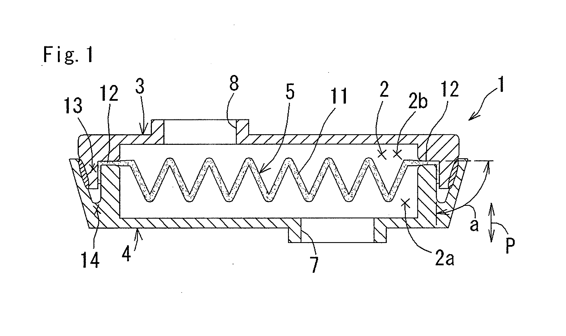
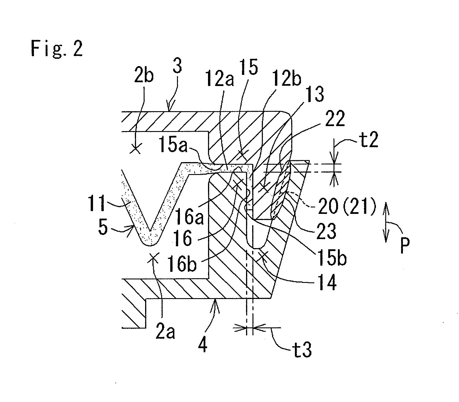
[0031]According to the filer of the present invention, since the holding portions, which hold the end portion of the filter medium, are spaced apart from the welded portions, which are welded together by the laser beam, the melting heat generated by the laser beam is not easily conducted to the filter medium, thus preventing undesirable effect on the shape or the quality of the material of the filter medium. Also, since the end portion of the filter medium is held in a bent position between the holding portions and the inner end portion of the filter medium is pressed by the vertical press surfaces in the joining direction, with the outer end portion of the filter medium being pressed by the lateral press surfaces in a direction intersecting the joining direction, the filter medium can be strongly supported between the two case members so as to prevent the filter medium from being dislodged when the filter is in use. Furthermore, since the first and second case members can be connected by a single execution of laser beam irradiation, the present invention provides an inexpensive and simply structured filter.
[0032]Additionally, in the case where the convex portion is provided along the periphery of one of the case members, the concave portion is provided along the periphery of the other case member, the holding portions are provided on the filter chamber side of where the convex portion engages the concave portion, and the welded portions are provided on the side of where the convex portion engages the concave portion opposite to the filter chamber, the convex portion engages the concave portion in a way that augments the mechanical bonding force during the welding by the laser beam and minimizes the warpage of the first and second case members, thus ensuring firm and secure joining of the case members. This structure also permits the holding portions to be sufficiently spaced apart from the welded portions and thus effectively inhibits the conduction of heat generated by the laser beam to the filter medium.
[0033]In the case where the convex portion and the concave portion have respective tapered abutment surfaces that abut with each other, this structure minimizes the gap at the engagement between the convex portion and the concave portion created by the warpage of the welded portions, thereby augmenting the welding strength therebetween.
[0034]In the filter of the present invention, the end portion of the filter medium is held between the holding portions in a bent position by joining the first case member and the second case member, and subsequently, a laser beam is irradiated to one of the first and second case members via the other case member so as to create the welded portions, thus connecting the first and second case members. In a filer thus provided, since the holding portions, which hold the end portion of the filter medium, are spaced apart from the welded portions, which are welded together by the laser beam, the melting heat generated by the laser beam is not easily conducted to the filter medium, thus preventing undesirable effect on the shape or the quality of the material of the filter medium. Also, the end portion of the filter medium is held in a bent position between the holding portions and the inner end portion of the filter medium is pressed by the vertical press surfaces in the joining direction, with the outer end portion of the filter medium being pressed by the lateral press surfaces in a direction intersecting the joining direction. Accordingly, the filter medium can be strongly supported between the two case members so as to prevent the filter medium from being dislodged when the filter is in use. Furthermore, since the first and second case members can be connected by a single execution of laser beam irradiation, the present invention provides an inexpensively and simply structured filter.

Problems solved by technology

However, this filter is not free from several disadvantages.
For example, since the filter is assembled by vibration welding, the upper and lower case members cannot be easily welded together immediately after the molding, thus lowering the production efficiency.
Moreover, the filter has limited design freedom as restrictions are imposed on the shapes of the cover members and the like.
This may cause the filter medium to be dislodged from the case members when the filter is in use.
Also in Patent Document 2, a laser beam needs to be irradiated twice to the case members, once from the X direction and once from the Y directions, which increases the overall cost and the cycle time for manufacturing the filter.

Method used


Image

  • Filter and manufacturing method therefor
  • Filter and manufacturing method therefor
  • Filter and manufacturing method therefor

Examples


examples

[0065]Hereinafter, an example of the present invention will be described in detail with reference to the attached drawings. Note that an oil filter for an automatic transmission of a vehicle is used as an example of a filter in the example.

(1) Filter Configurations

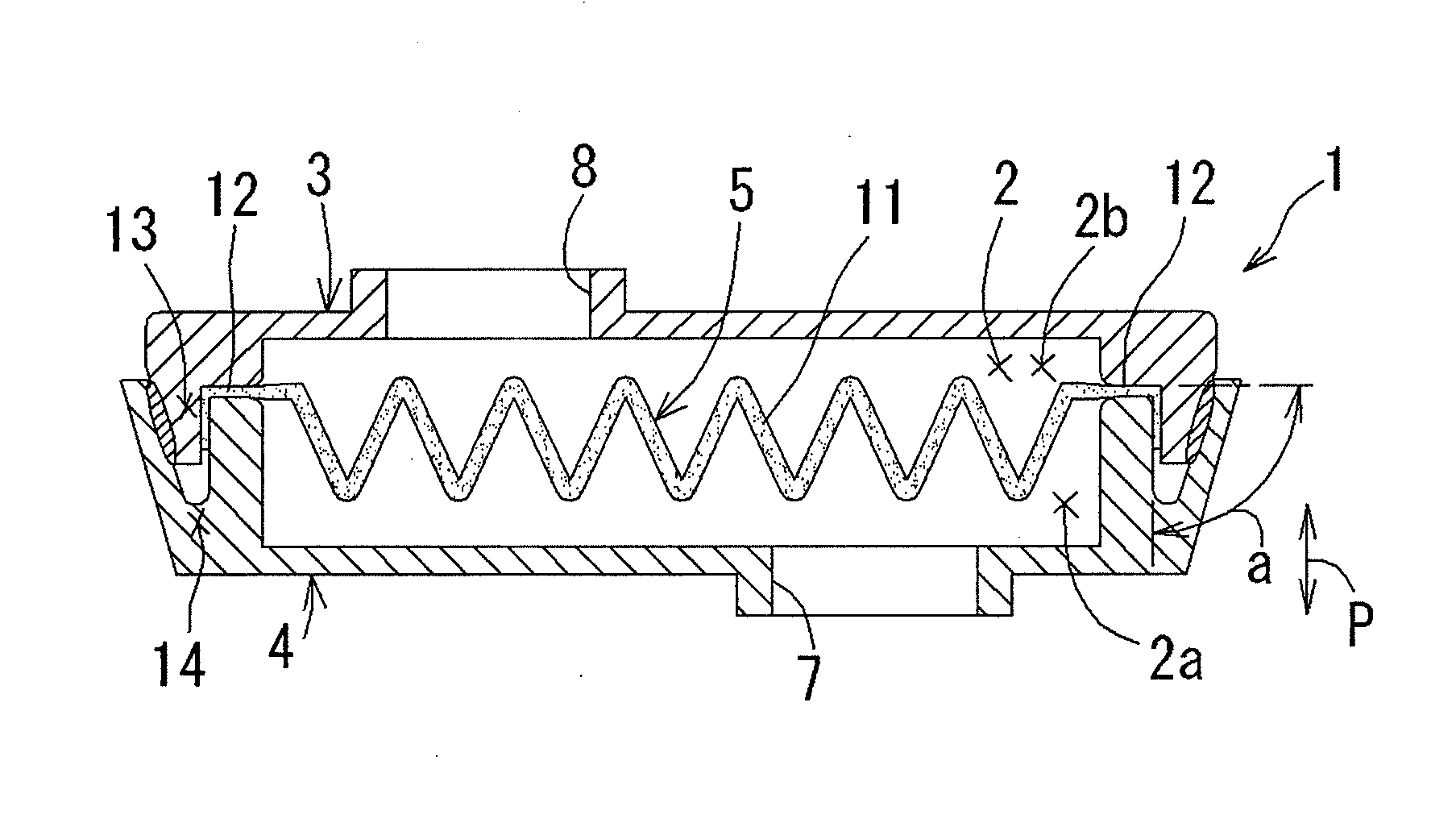
[0066]As shown in FIG. 1, a filter 1 of this example includes an upper case member 3 (which is an example of a first case member according to the present invention), and a lower case member 4 (which is an example of a second case member according to the present invention), which are joined together to form a filter chamber 2 therebetween. The filter 1 also includes a filter medium 5 with an end portion 12 held between the upper and lower case members 3 and 4.

[0067]The lower case member 4 has a fluid inlet 7 formed therein to introduce an unfiltered fluid, whereas the upper case member 3 has a fluid outlet 8 formed therein to discharge the fluid after it is filtered by the filter medium 5. The upper case member 3 is made of...


PUM


Abstract

The filter 1 includes a first case member (an upper case member), a second case member (a lower case member) that are mutually joined to form a filter chamber therebetween, and a filter medium with an end portion held between the first and second case members. The first and second case members include holding portions, respectively, for holding the end portion of the filter medium in a bent position and welded portions, respectively, which are spaced apart from the holding portions and are welded together by a laser beam. The holding portions include vertical press surfaces, respectively, for pressing an inner end portion of the filter medium in the joining direction between the case members. The holding portions also include lateral press surfaces and, respectively, for pressing an outer end portion of the filter medium in a direction intersecting the joining direction.

Description

BACKGROUND OF THE INVENTION [0001]1. Field of the Invention[0002]The present invention relates to a filter and a manufacturing method therefor. More particularly, the present invention relates to an inexpensive and simply constructed filter capable of suppressing dislodgement of a filter medium during filter use and a manufacturing method therefor.[0003]2. Description of the Related Art[0004]An oil filter for an automatic transmission is known in which a first case member and a second case member are mutually joined to form a filter chamber, and a filter element is held between joining ends thereof (see Patent Documents 1, for example).[0005]Patent Document 1 discloses one such filter that includes an upper cover member 14 and a lower cover member 16 joined together by causing spikes 56 on the lower cover member 16 to penetrate edges of a filter medium 20 and performing vibration welding to fuse a rib 60 located outwardly from the spikes 56. However, this filter is not free from sev...

Claims


Application Information

Patent Timeline
IPC IPC(8): B01D35/30B01D29/05B01D27/08B01D39/00F16H57/04
CPCB01D29/012B29C66/5412B29C66/322B29K2023/0633B29K2023/12B29K2025/00B29K2059/00B29K2067/00B29K2067/006B29K2069/00B29K2077/00B29K2105/206B29K2305/00B29K2995/0039B29K2995/0041B29L2031/14F16H57/04B29C65/1635B29C66/12469B29C66/12445B29C66/12463B29C66/12464B01D29/07B29C66/8322B29C66/73921B29C66/73772B29C66/73776B29K2995/0027B29C66/71B29K2067/003B29K2025/06
Inventor GOTO, TATSUYA
Owner TOYOTA BOSHOKU KK
Learn More