Storage apparatus and control method

a technology of storage apparatus and control method, which is applied in the direction of recording information storage, maintaining head carrier alignment, instruments, etc., can solve the problems of lowering device performance, lowering device performance, and vibration produced in the actuator during seeking, so as to enhance device performance

Inactive Publication Date: 2008-07-17
TOSHIBA STORAGE DEVICE CORP
View PDF8 Cites 9 Cited by
  • Summary
  • Abstract
  • Description
  • Claims
  • Application Information

AI Technical Summary

Benefits of technology

[0021]According to the present invention, the coil vibration in time of seek and in time of settling is detected by the sensor attached to the actuator, and the actuator is drive controlled such that the head position error signal is reduced based on the vibration detected signal, whereby the seek residual vibration by seek operation is reduced, the settling time from t

Problems solved by technology

However, in such conventional magnetic disk device, vibration may produce in the actuator during seeking due to mechanical accuracy such as parallelism of the coil supported by the actuator and the yoke fixed and arranged on the housing side.
Therefore, seek residual vibration leads to lowering of device performance.
However, the control of detecting and suppressing the vibration of the actuator by the sensor of patent document 1 is performed during on-track, and does not address the seek residual vibration produced dur

Method used


Image

  • Storage apparatus and control method
  • Storage apparatus and control method
  • Storage apparatus and control method

Examples


Embodiment Construction

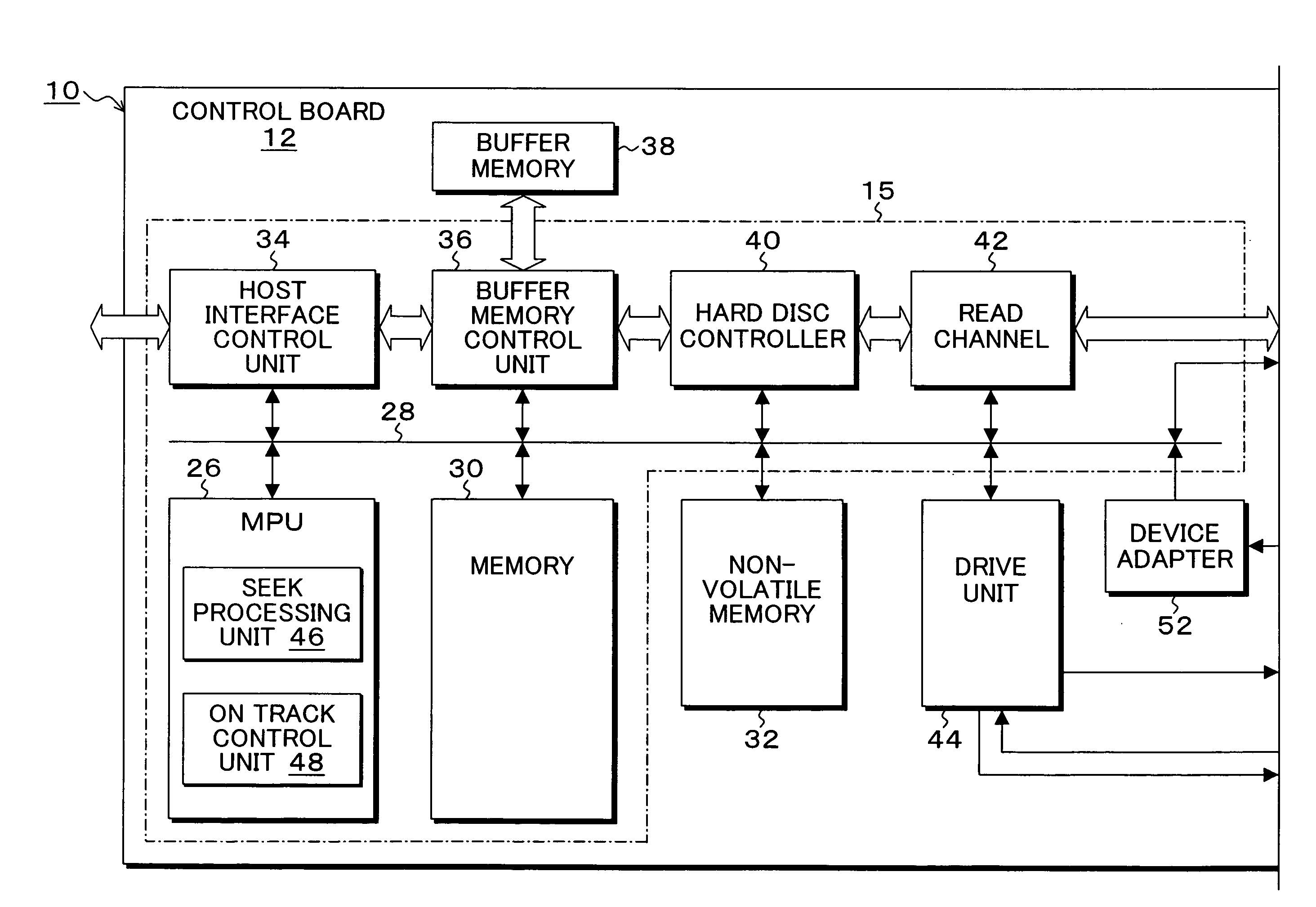
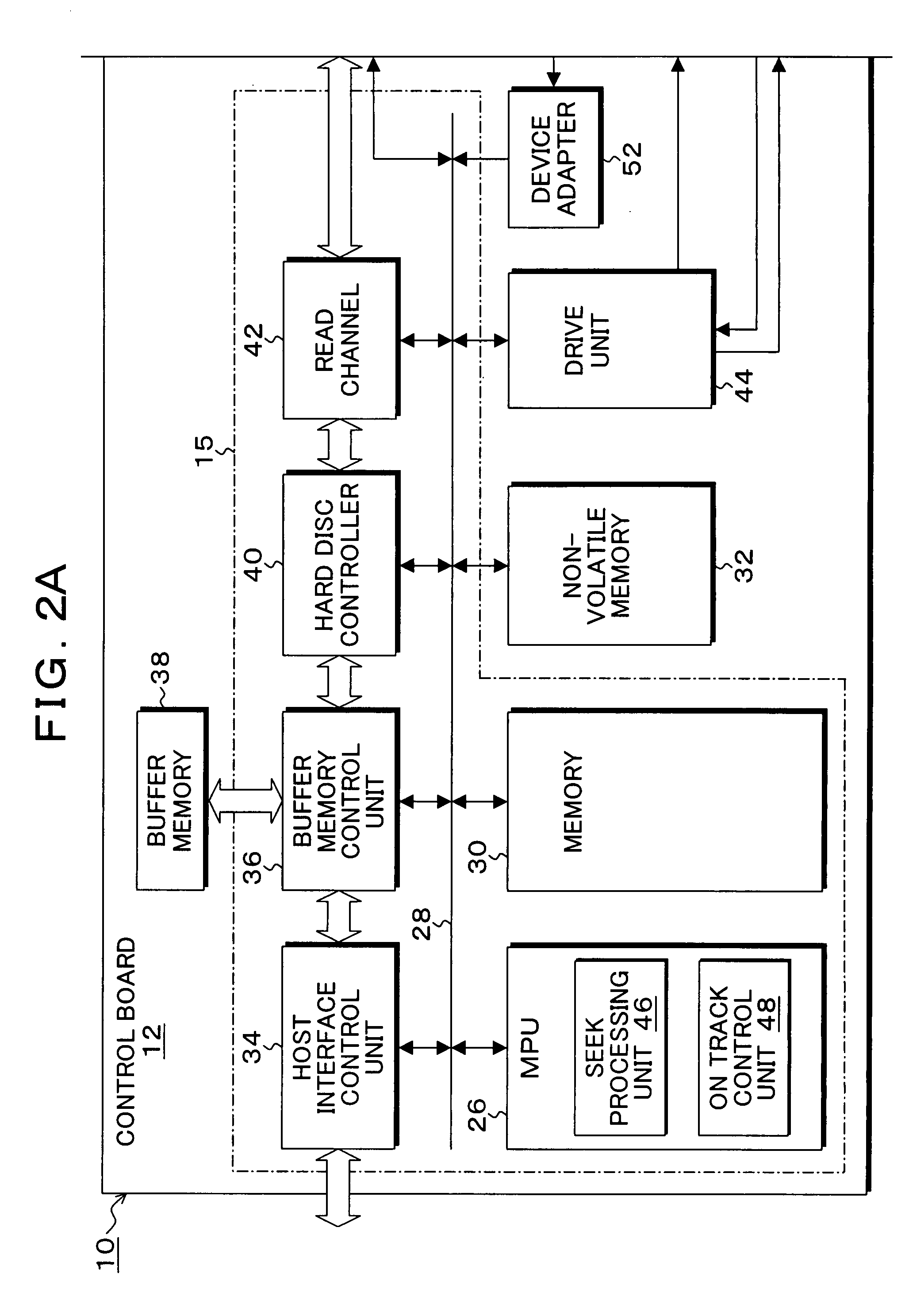
[0040]FIGS. 2A and 2B are block diagrams showing an embodiment of a magnetic disk device according to the present invention. In FIGS. 2A and 2B, a magnetic disk device 10 known as hard disk drive (HDD) is configured by a disk enclosure 14 and a control board 12. A spindle motor (SPM) 16 is arranged on the disk enclosure 14, and magnetic disks (recording media) 20-1, 20-2 are attached to a rotating shaft of the spindle motor 16 and rotated for a constant time at 4200 rpm, and the like. A voice coil motor (VCM) 18 is arranged on the disk enclosure 14, which voice coil motor 18 is mounted with heads 22-1 to 22-4 at an arm distal end of an actuator to position the heads with respect to the recording surfaces of the magnetic disks 20-1, 20-2. A recording element and a reading element are integrated and mounted on the head 22-1 to 22-4. The heads 22-1 to 22-4 are signal line connected to a head IC 24, and the head IC 24 selects one head with a head select signal based on a write command o...


PUM


Abstract

An actuator supports a head at one end of a rotatably supported shaft unit and supports a coil of a voice coil motor at the other end, and moves the head to an arbitrary track position of a recording medium. A sensor, attached to a coil support unit of the actuator, detects the coil vibration and outputs a vibration detected signal. A control unit controls the actuator to reduce a head position error signal based on the vibration detected signal of the sensor in time of seek and in time of settling of moving the head to a target track position on the medium through drive of the actuator and drawing the same. The vibration detected signal of the sensor includes bending vibration component of the coil and the twisting vibration component of the coil when the actuator is driven.

Description

[0001]This application is a priority based on prior application No. JP 2007-005506, filed Jan. 15, 2007, in Japan.BACKGROUND OF THE INVENTION[0002]1. Field of the Invention[0003]The present invention relates to a storage apparatus and control methods for detecting coil vibration generated in time of actuator drive and performing a control such that a head position error signal reduces based on the vibration detected signal, in particular, to a storage apparatus and a control method for detecting coil vibration in time of seek for positioning the head at a target track and in time of settling, and performing a control such that the head position error signal reduces based on the vibration detected signal.[0004]2. Description of the Related Arts[0005]Conventionally, a rotary actuator is driven by a voice coil motor in the magnetic disk device to move the head to an arbitrary target track of a magnetic disk medium to write data to the target track or to read the data already written on...

Claims


Application Information

Patent Timeline
IPC IPC(8): G11B21/02
CPCG11B5/5582G11B21/02G11B21/10
Inventor FUNABASHI, KEIYAMADA, TOMOYOSHIHARA, TAKEYORI
Owner TOSHIBA STORAGE DEVICE CORP
Why Eureka
Try Eureka