Loudspeaker System

a technology of loudspeaker and speaker, which is applied in the direction of transducer details, electrical transducers, electrical apparatus, etc., can solve the problems that the loudspeaker system has had difficulties in realizing a loudspeaker system, and achieve the effect of reducing the volume of the gas absorption material itself, and reducing the volume of the loudspeaker system

Inactive Publication Date: 2008-07-17
PANASONIC CORP
View PDF4 Cites 44 Cited by
  • Summary
  • Abstract
  • Description
  • Claims
  • Application Information

AI Technical Summary

Benefits of technology

[0031]According to the above-mentioned first aspect, since the average particle diameter of the gas absorption material is less than 0.1 mm, a ratio of a volume of the micropore which physically absorbs the gas is large as compared with that of the conventional gas absorption material whose average grain diameter is greater than or equal to 0.1 mm. Therefore, a volume expansion ratio of the gas absorption material whose average particle diameter is less than 0.1 mm is large as compared with that of the conventional one. The volume expansion ratio markedly increases in a range in which the average particle diameter is less than 0.1 mm. Thus, by using the gas absorption material whose average particle diameter is less than 0.1 mm, a sufficiently great volume expansion effect can be obtained as compared with a case where the conventional gas absorption material whose average grain diameter is greater than or equal to 0.1 mm is used. As a result, in a case where a volume of the gas absorption material is the same as that of the conventional one, a low frequency band can be further expanded as compared with that of the conventional one. In a case where the same width of the low frequency band as that of the conventional one is expanded, a volume of the gas absorption material itself can be reduced as compared with that of the conventional one. As a result, the loudspeaker system can be downsized as compared with the conventional one. In addition, according to the first aspect of the present invention, since a ratio of a volume of the macropores formed in the gas absorption material is small as compared with that of the conventional one, the effect of functioning as a high-cut filter, which is caused by the macropores, can be reduced.

Problems solved by technology

Due to an influence of an acoustic stiffness which an internal space of a cabinet causes, a conventional loudspeak

Method used


Image

  • Loudspeaker System
  • Loudspeaker System
  • Loudspeaker System

Examples


first embodiment

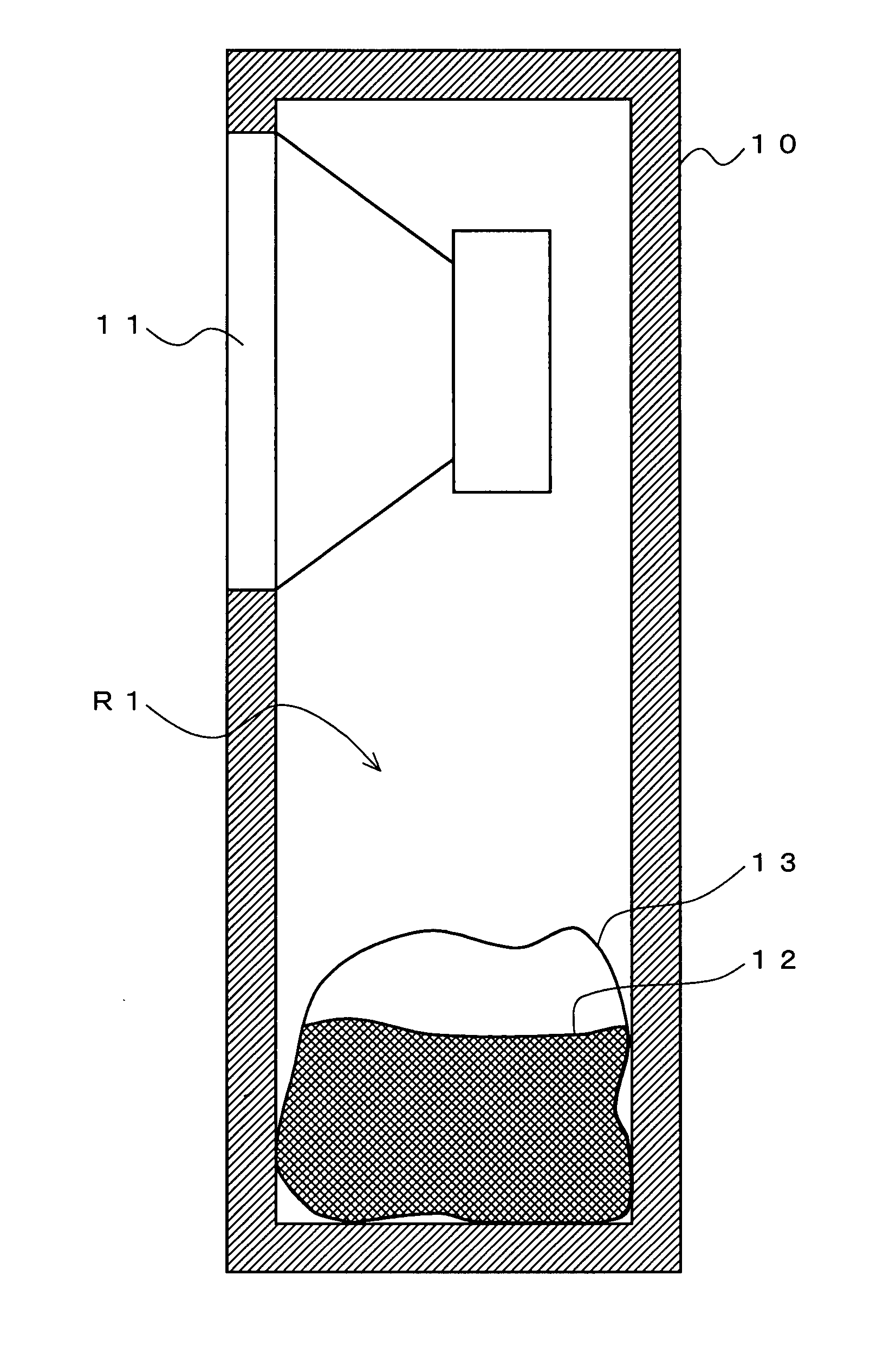
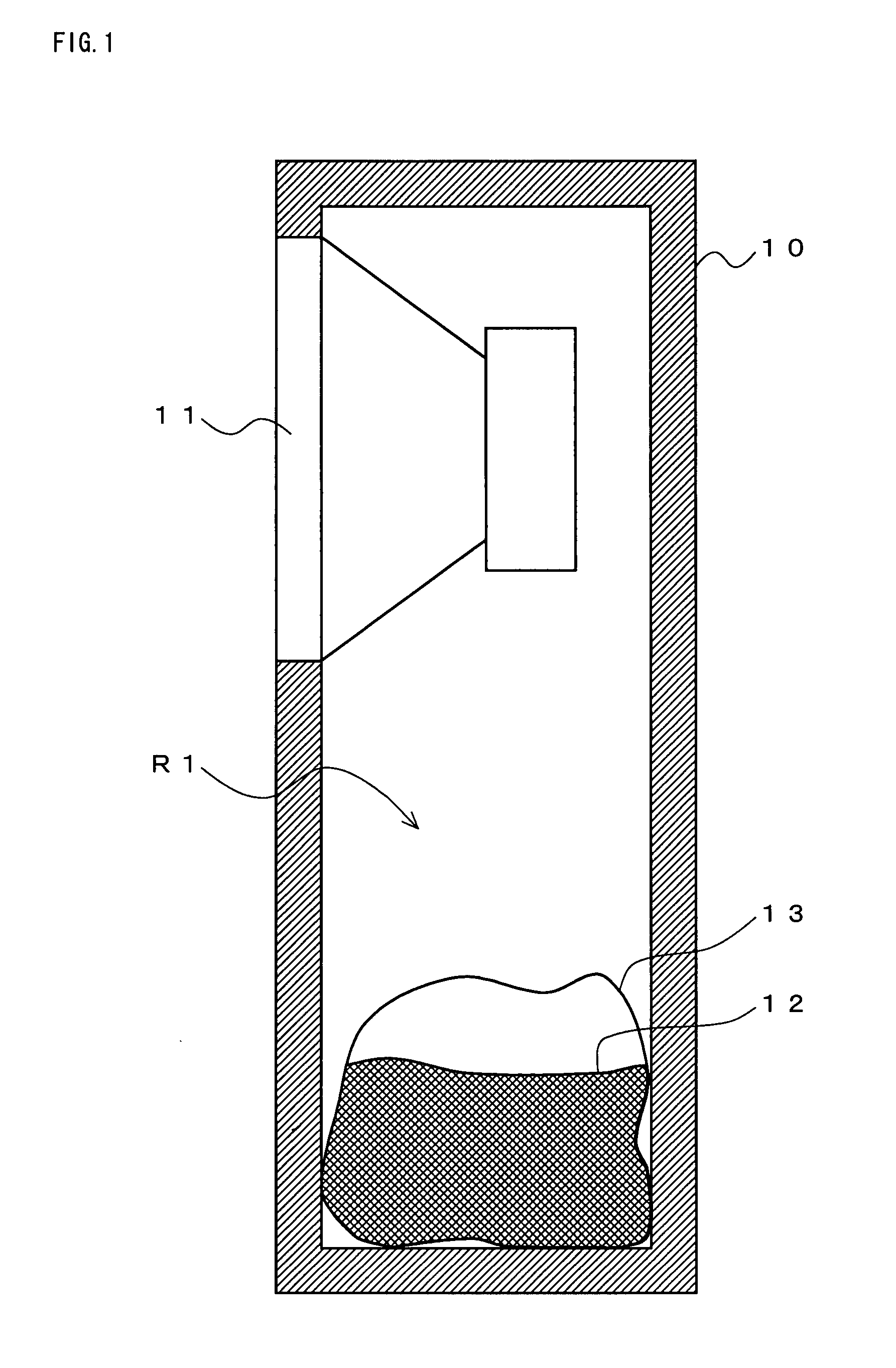
[0100]Referring to FIG. 1, a loudspeaker system according to a first embodiment of the present invention will be described. FIG. 1 is a tectonic profile showing one example of the loudspeaker system according to the first embodiment. In FIG. 1, the loudspeaker system comprises a cabinet 10, a speaker unit 11, a gas absorption material 12, and a blocking member 13. The loudspeaker system shown in FIG. 1 is a closed-type loudspeaker system.

[0101]The speaker unit 11 is, for example, an electrodynamic-type speaker. The speaker unit 11 is mounted at an opening formed on an upper portion of a front face of the cabinet 10. The gas absorption material 12 is powdery activated carbon with an average particle diameter of 0.01 to 0.03 mm (hereinafter, referred to as powdery activated carbon). The above-mentioned powdery activated carbon is produced by crushing activated carbon, which is made from a plant-derived material, for example, coconut husks, so as to be in a powdery state with an averag...

second embodiment

[0114]Referring to FIG. 4, a loudspeaker system according to a second embodiment of the present invention will be described. FIG. 4 is a tectonic profile illustrating one example of the loudspeaker system according to the second embodiment. The loudspeaker system according to the present embodiment is different from the loudspeaker system according to the first embodiment in that the loudspeaker system according to the second embodiment, which includes a passive radiator 21, is the so-called phase-inversion-type loudspeaker system. Herein under, different points will be mainly described.

[0115]In FIG. 4, the loudspeaker system comprises a cabinet 20, a speaker unit 11, a gas absorption material 12, a blocking member 13, the passive radiator 21, and a partition plate 22. Since the speaker unit 11, the gas absorption material 12, and the blocking member 13 shown in FIG. 4 are the same as those in the above-described first embodiment, the same numerals are used and descriptions thereof ...

third embodiment

[0124]Referring to FIG. 7, a loudspeaker system according to a third embodiment of the present invention will be described. FIG. 7 is a diagram illustrating a sectional side view and a rear view, a part of which is a sectional view, of one example of the loudspeaker system according to the third embodiment. The loudspeaker system according to the present embodiment is different from the loudspeaker system according to the first embodiment in that the loudspeaker system according to the third embodiment, which includes an acoustic port 31, is the so-called phase inversion type system. Also the loudspeaker system according to the present embodiment is different from the loudspeaker system according to the first embodiment in that the loudspeaker system according to the third embodiment further includes a segmentation arrangement mechanism 32 in which a gas absorption material 12 is arranged so as to be segmented.

[0125]In FIG. 7, the loudspeaker system comprises, a cabinet 30, a speake...


PUM


Abstract

A loudspeaker system according to the present invention comprises a cabinet, a speaker unit mounted in the cabinet, and a powdery gas absorption material which is disposed in an internal space of the cabinet and physically absorbs gas being present in the internal space of the cabinet. An average particle diameter of the gas absorption material is less than 0.1 mm. Thus, according to the present invention, the loudspeaker system which expands a low frequency band, prevents a reduction in an acoustic pressure level, exhibits a volume expansion effect also in a high frequency band of 100 to 200 Hz or more, is compact, and enables enriched bass reproduction can be realized.

Description

TECHNICAL FIELD[0001]The present invention relates to a loudspeaker system and more particularly, to a loudspeaker system, having a small-sized cabinet, which realizes enriched bass reproduction.BACKGROUND ART[0002]Due to an influence of an acoustic stiffness which an internal space of a cabinet causes, a conventional loudspeaker system has had difficulties in realizing a loudspeaker system which is compact and capable of reproducing bass. Limitations in this bass reproduction depend on a magnitude of the acoustic stiffness, namely a volumetric capacity of an inside of the cabinet. Therefore, as a solution to the problem of these limitations in bass reproduction, there has been a loudspeaker system in which a block of activated carbon is disposed inside of a cabinet (for example, refer to patent document 1).[0003]FIG. 18 is a tectonic profile of a major portion of a conventional loudspeaker system. In FIG. 18, the conventional loudspeaker system comprises a cabinet 90, a woofer 91, ...

Claims


Application Information

Patent Timeline
IPC IPC(8): H04R1/02
CPCH04R1/2803H04R1/2819H04R2499/15H04R2499/11H04R2499/13H04R1/2834
Inventor SAIKI, SHUJIMATSUMURA, TOSHIYUKI
Owner PANASONIC CORP
Why Eureka
Try Eureka