
Apparatus for and method of radio link establishment between two communication devices

a technology of radio link and apparatus, applied in the field of data communication, can solve problems such as even bigger problems

Inactive Publication Date: 2008-07-17
TEXAS INSTR INC
View PDF6 Cites 90 Cited by
  • Summary
  • Abstract
  • Description
  • Claims
  • Application Information

AI Technical Summary

Benefits of technology

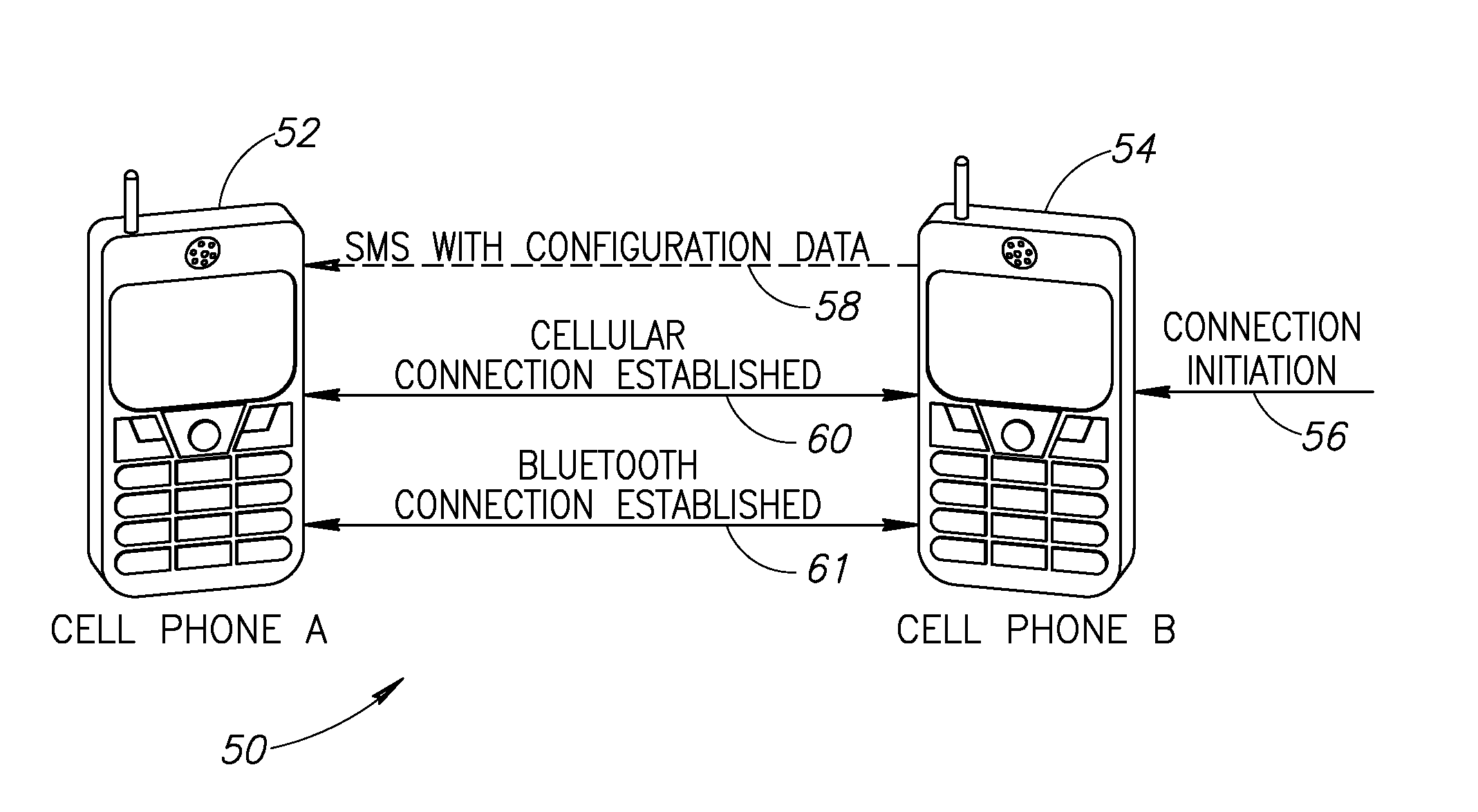
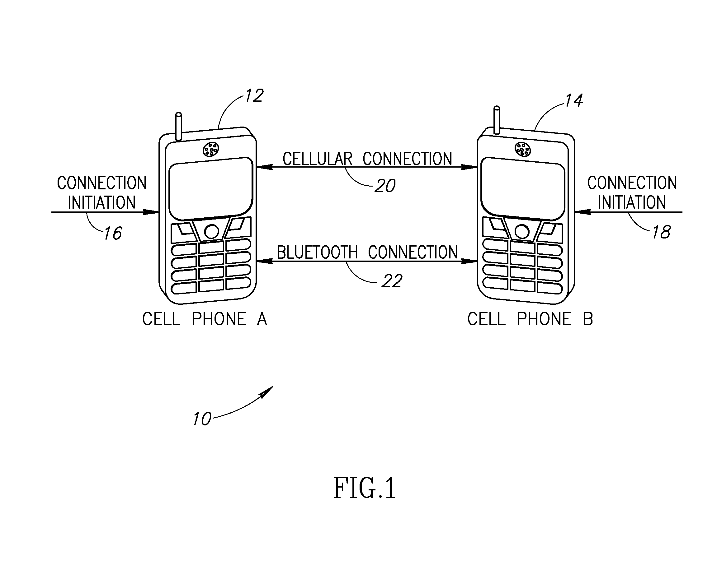
[0007]The present invention is a novel and useful apparatus for and method of automatically establishing a secondary communications link (e.g., short range wireless connection) between two communications devices utilizing an already established primary communications connection (e.g., cellular phone connection). The invention eliminates the need for both sides of a connection to manually initiate and configure their communication devices in order to establish a wireless connection. The mechanism of the invention is particularly applicable to wireless communication devices that incorporate secondary wireless connection technology such as any of the short range wireless standards currently in use. Examples of short range wireless technologies in common use today include wireless local area network (WLAN), Bluetooth and Ultra Wideband (UWB).
[0010]One advantage of the automatic link establishment mechanism is that it permits the communication devices to keep their secondary link radios off thus significantly reducing power consumption and extending the life of battery dependent mobile devices. Thus, the invention saves power while maintaining constant secondary link connectivity of the communications device without requiring user configuration on the target or destination side of the connection.

Problems solved by technology

In WLAN networks, this problem is even bigger since in WLAN networks there are numerous parameters that much be configured between both sides before any communications can occur.

Method used


Image

  • Apparatus for and method of radio link establishment between two communication devices
  • Apparatus for and method of radio link establishment between two communication devices
  • Apparatus for and method of radio link establishment between two communication devices

Examples


Embodiment Construction

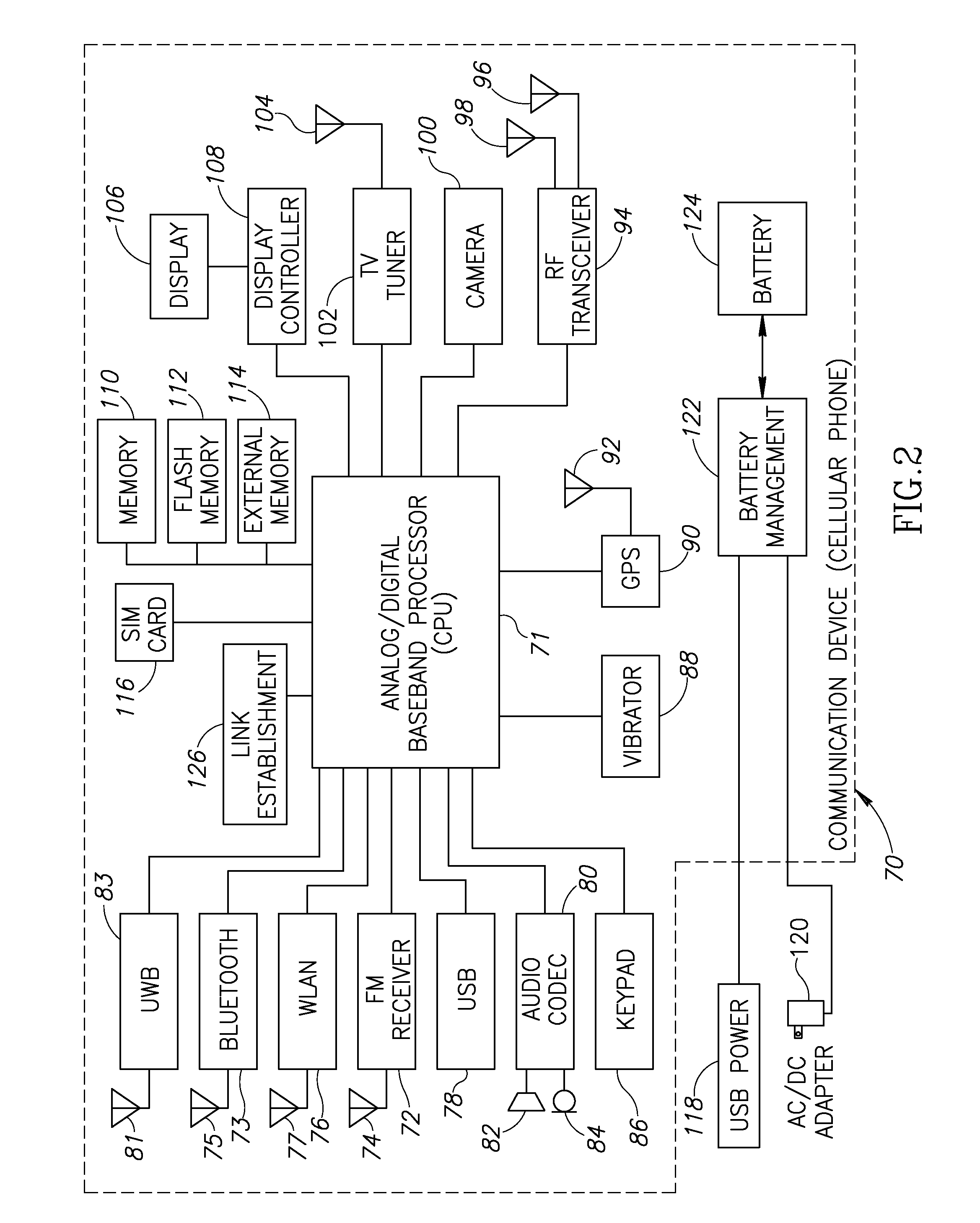
Notation Used ThroughoutThe following notation is used throughout this document.TermDefinitionACAlternating CurrentASICApplication Specific Integrated CircuitAVIAudio Video InterleaveBMPWindows BitmapBTBluetoothCPUCentral Processing UnitDCDirect CurrentDHCPDynamic Host Control ProtocolDSPDigital Signal ProcessorDTMFDual Tone, Multiple FrequencyEPROMErasable Programmable Read Only MemoryFMFrequency ModulationFPGAField Programmable Gate ArrayGPSGround Positioning SatelliteHDLHardware Description LanguageIEEEInstitute of Electrical and Electronics EngineersIPInternet ProtocolJPGJoint Photographic Experts GroupLANLocal Area NetworkMACMedia Access ControlMP3MPEG-1 Audio Layer 3MPGMoving Picture Experts GroupPDAPortable Digital AssistantRAMRandom Access MemoryRFRadio FrequencyROMRead Only MemorySIMSubscriber Identity ModuleSMSShort Message ServiceSSIDService Set IdentifierTVTelevisionUSBUniversal Serial BusUWBUltra WidebandWEPWired Equivalent PrivacyWLANWireless Local Area NetworkWMAWindo...


PUM


Abstract

A novel and useful apparatus for and method of automatically establishing a secondary communications link (e.g., short range wireless connection such as WLAN, Bluetooth, etc.) between two communications devices utilizing an already established primary communications connection (e.g., cellular phone connection). The invention eliminates the need for both sides of a connection to manually initiate and configure their communication devices in order to establish a wireless connection. Connection parameters required to establish the link are configured on only one communication device (e.g., cellular phone), without the need to also configure them on the communication device on the other end of the connection. Messages containing the connection parameters are sent from the requesting (or initiating) side over the established primary connection to the target or destination side of the connection.

Description

FIELD OF THE INVENTION[0001]The present invention relates to the field of data communications and more particularly relates to an apparatus, method and system for establishing a radio link between two communication devices, such as cellular phones.BACKGROUND OF THE INVENTION[0002]Currently there are numerous consumer electronics communications devices such as portable multimedia players, add-ons for portable multimedia players, cellular telephones, personal digital assistants (PDAs), etc. that support a primary communications connection in addition to one or more secondary communications connections. Considering communication devices such as cellular phones, for example, an increasing number of cellular phones today support both the basic primary cellular communications connection as well as support one or more secondary connections such as Bluetooth and Wireless Local Area Network (WLAN) which permit direct connection between cellular phones. Other short distance wireless technolog...

Claims


Application Information

Patent Timeline
Patent Type & Authority Applications(United States)
IPC IPC(8): H04Q7/20H04B7/26H04W76/02H04W88/06
CPCH04W88/06H04W76/025H04W76/15
Inventor IRONY, RANSHERMAN, ITAY
Owner TEXAS INSTR INC
Learn More