
Vehicle body frame

a frame and vehicle technology, applied in the field of vehicle frame, can solve the problems of difficult to secure a and achieve the effect of sufficient energy absorption amount of the fram

Inactive Publication Date: 2008-07-24
HONDA MOTOR CO LTD
View PDF2 Cites 16 Cited by
  • Summary
  • Abstract
  • Description
  • Claims
  • Application Information

AI Technical Summary

Benefits of technology

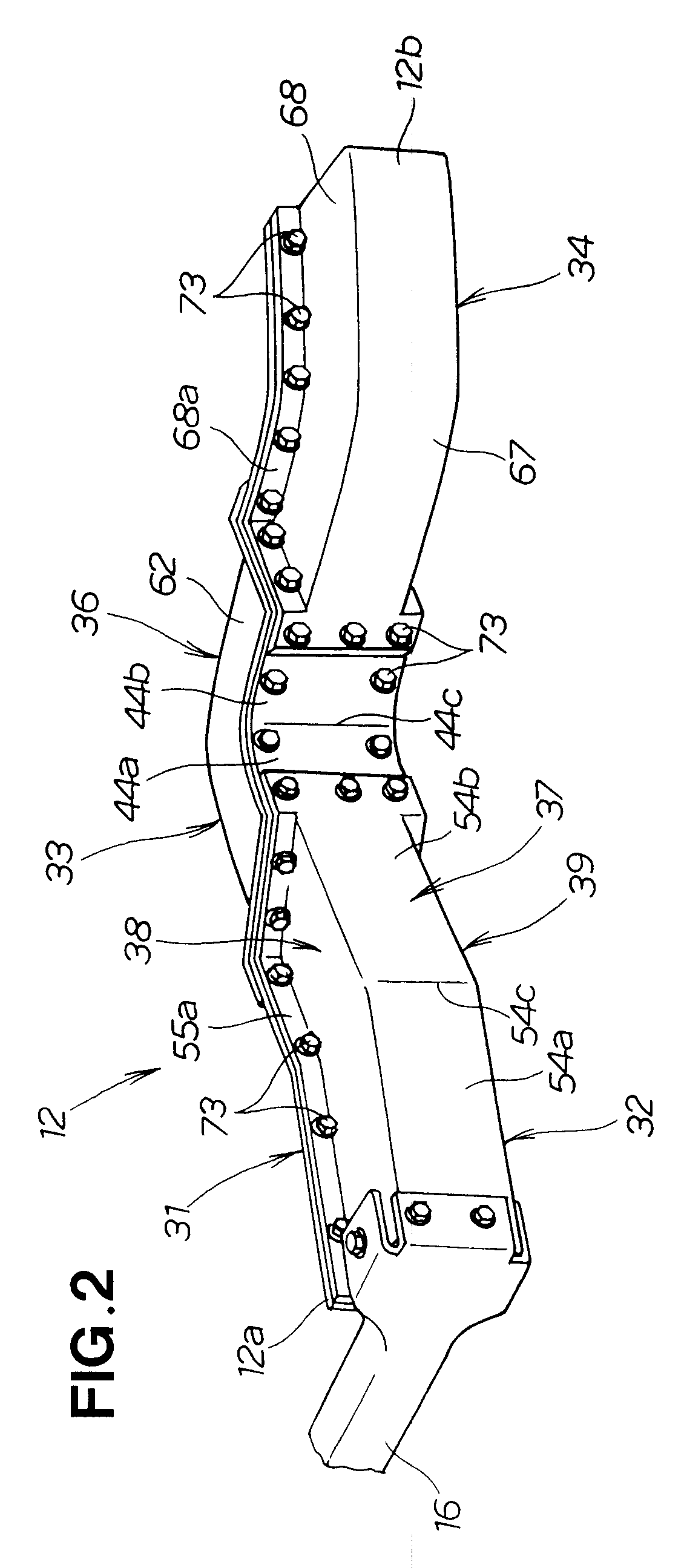
[0009]According to the present invention, the main frame section is made of the light alloy material, such as aluminum alloy, and thus, it can have an increased thickness and hence an increased resistive strength against a buckling stress. The steel material, on the other hand, has a greater resistive strength against a tensile stress and a greater maximum elongation amount than the light alloy material. Thus, in the present invention, the compression wall portion is formed by the main frame section made of light alloy, while the tension wall portion is formed by the sub-frame section made of steel.
[0010]Because the compression wall portion is formed by the main frame section made of light alloy, it can be formed into a greater thickness than the sub-frame section, and such a great thickness can achieve an increased resistive strength of the compression wall portion against a buckling stress. Further, because the tension wall portion is formed by the sub-frame section made of steel that has a greater resistive strength against a tensile stress and a greater maximum elongation amount than the light alloy material, it can achieve an increased energy absorption amount.
[0012]Thus, with the simple construction of merely attaching the sub-frame section made of steel to the main frame section made of light metal, it is possible to readily achieve a sufficient energy absorption amount of the vehicle body frame having a bent portion. In addition, because the present invention can readily secure a sufficient rigidity of the vehicle body frame having the bent portion, it is possible to secure a space for accommodating an engine, front road wheel, etc. As a result, it is possible to enhance a degree of layout freedom of the engine, front road wheel, etc.

Problems solved by technology

With such a vehicle body frame having bent portions, however, it is difficult to secure a sufficient energy absorption amount when an impact has been applied to a front portion of the vehicle body frame; thus, it has been conventional to achieve a sufficient energy absorption amount, such as by increasing the thickness of the vehicle body frame.

Method used


Image

  • Vehicle body frame
  • Vehicle body frame
  • Vehicle body frame

Examples


first embodiment

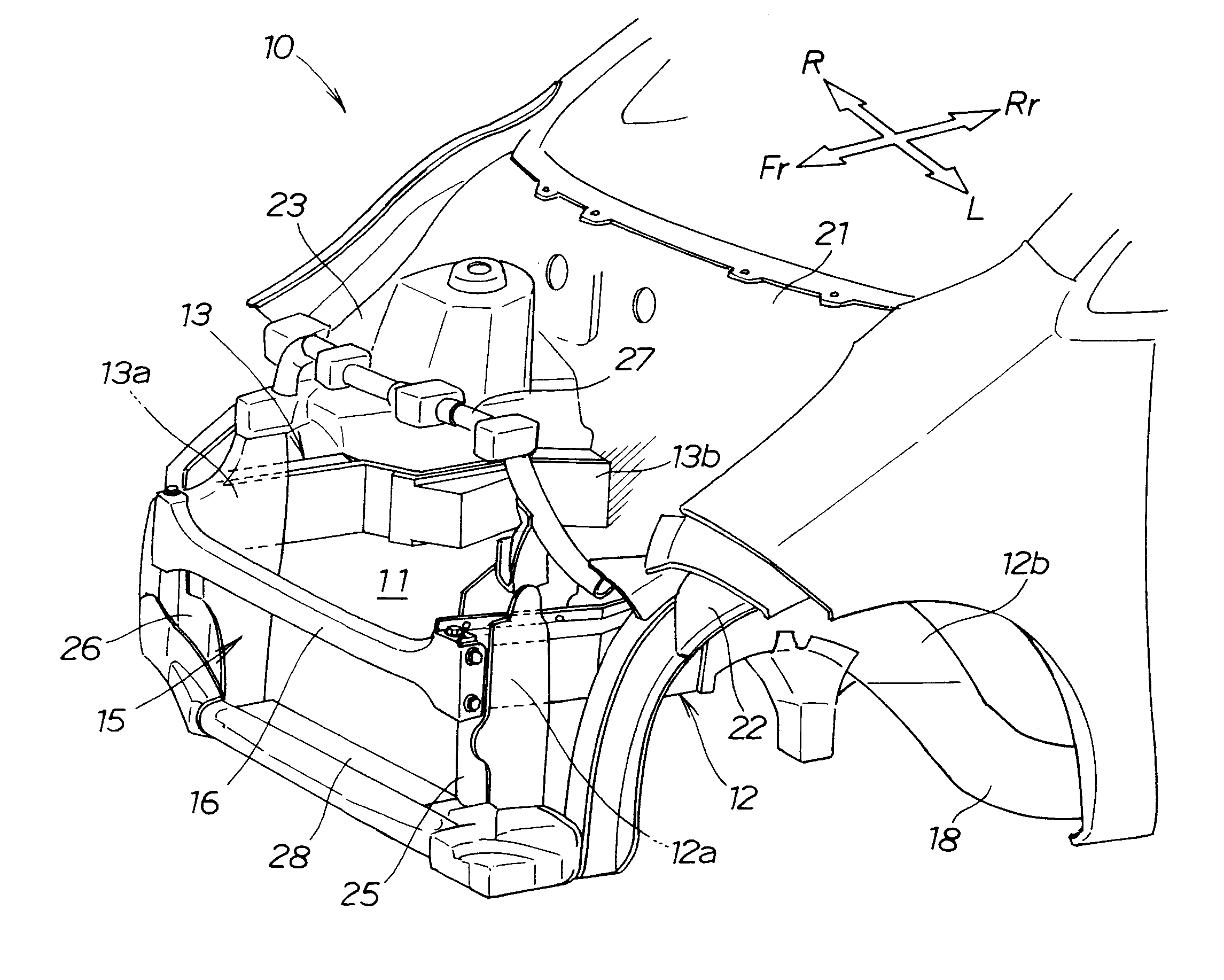
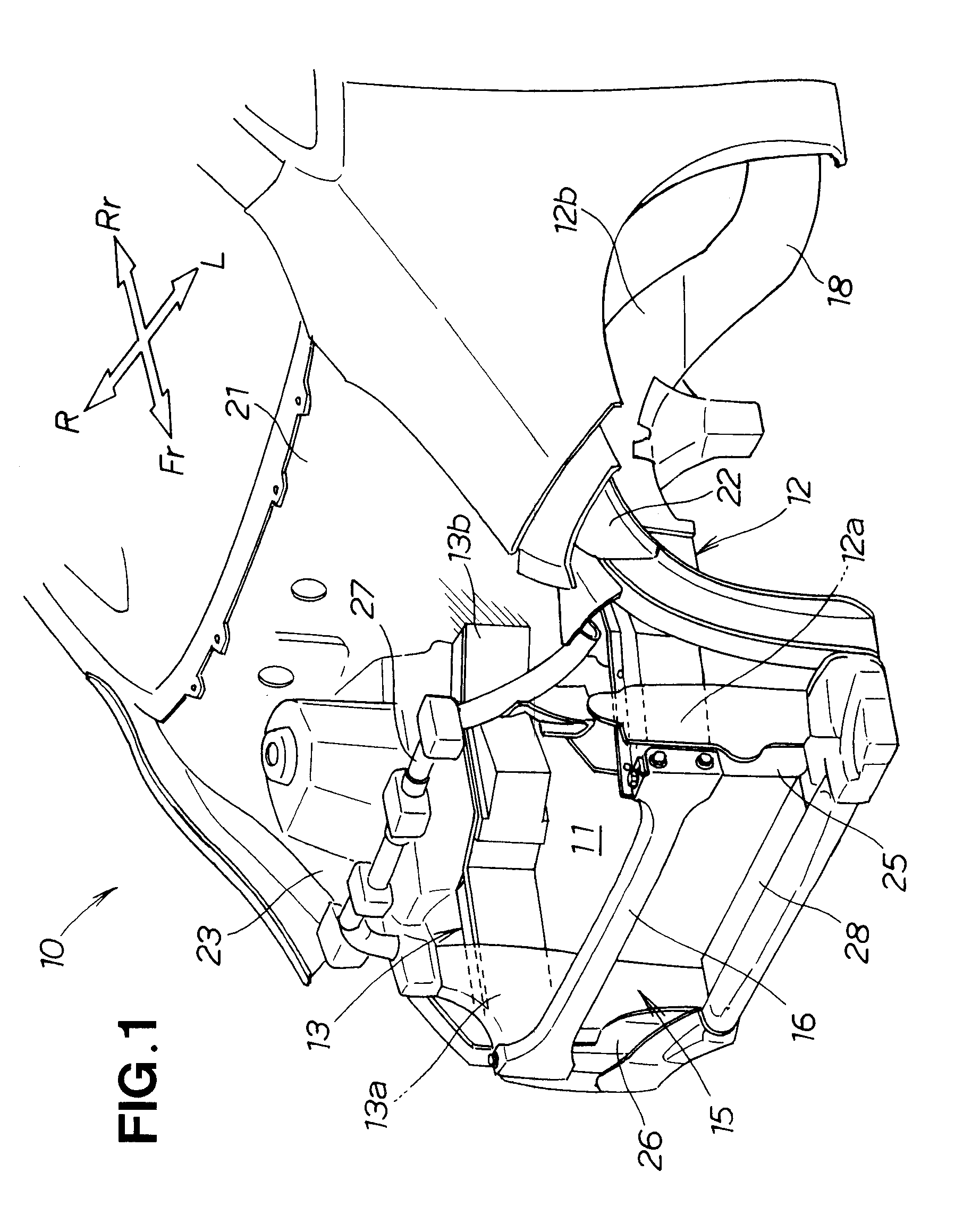
[0027]FIG. 1 is a perspective view showing a front vehicle body structure 10 provided with vehicle body frames according to a first embodiment of the preset invention. The front vehicle body structure 10 includes: left and right front side members (hereinafter referred to as “left and right vehicle body frames”) 12 and 13 that define left and right frames of an engine room 11; a bulkhead 15 provided on left and right front end portions 12a and 13a of the left and right vehicle body frames 12 and 13; a connection bar 16 connecting between the front end portions 12a and 13a of the vehicle body frames 12 and 13; left and right outriggers 18 (the right outrigger is not shown); and a lower dashboard section 21 provided on the left and right outriggers 18 and rear end portions 12b and 13b of the left and right vehicle body frames 12 and 13.

[0028]Engine / transmission unit 19 (FIG. 3) is disposed transversely in the engine room 11. The engine / transmission unit 19 is a unit where a transmissi...

second embodiment

[0086]FIG. 7 is an exploded perspective view showing the second embodiment of the vehicle body frame 90 of the present invention, which is similar to the first embodiment except that it includes a modified main frame section 91 in place of the main frame section 31 employed in the first embodiment of the vehicle body frame 12.

[0087]The main frame section 91 is similar to the main frame section 31 but different therefrom in that it has a pair of first upper and lower horizontal reinforcing ribs 92 formed on the outer surface of the front compression wall portion 42, a pair of second upper and lower horizontal reinforcing ribs 93 formed on the inner surface of the middle compression wall portion 44 and a pair of third upper and lower horizontal reinforcing ribs 94 formed on the outer surface of the rear compression wall portion 46. Similarly to the main frame section 31 in the first embodiment, the main frame section 91 may be formed by casting.

[0088]The first upper and lower horizont...

third embodiment

[0096]FIG. 9 is an exploded perspective view showing the third embodiment of the vehicle body frame of the invention, and FIG. 10 is a plan view of the third embodiment.

[0097]The third embodiment of the vehicle body frame 100 includes a modified main frame section 101 made of light metal and formed into a generally “U” (or channel) sectional shape so that the main frame section 101 has upper and lower flanges 115 and 116 provided centrally in the width direction of the vehicle body frame 100. The main frame section 101 also has vertical reinforcing ribs 103, 104 and 105 provided in a space defined by the “U” (or channel) sectional shape.

[0098]The vehicle body frame 100 includes: a main frame section 101 made of light metal; a front sub-frame section 111 made of steel and fixedly mounted to a front portion 107 of the main frame section 101; a middle sub-frame section 112 made of steel and fixedly mounted to a middle portion 108 of the main frame section 101; and a rear sub-frame sect...


PUM


Abstract

Vehicle body frame includes a main frame section that is made of light metal and extends in a band shape from a front end portion to a rear end portion of the vehicle body frame to thereby form a compression wall portion, and a sub-frame section that is made of steel and fixedly mounted along the band-shaped main frame section. The sub-frame section forms a hollow structure in conjunction with the main frame section and forms a tension wall portion. The main frame section has a greater thickness than the sub-frame section.

Description

FIELD OF THE INVENTION[0001]The present invention relates to vehicle body frames which include parts where are produced a compressive stress and tensile stress when an impact acts on the vehicle body frame.BACKGROUND OF THE INVENTION[0002]Among the known front vehicle body structures are ones having left and right front side members (hereinafter referred to as “vehicle body frames”) made of a light alloy material, such as aluminum alloy, as disclosed, for example, in Japanese Patent Application Laid-Open Publication Nos. HEI-11-208519 (JP-A-11-208519) and 2003-72587 (JP-A-2003-72587).[0003]Each of the vehicle body frames disclosed in JP-A-11-208519 and JP-A-2003-72587 is a hollow, tubular structure which has an outer wall formed into a regular polygonal shape (e.g., regular hexagonal shape) and a plurality of radial ribs connecting between the individual apexes and the central axis of the outer wall. With each of these disclosed vehicle body frames, which is made of a light alloy ma...

Claims


Application Information

Patent Timeline
IPC IPC(8): B62D21/00
CPCB62D21/152B62D29/008B62D27/065
Inventor YAMADA, TAKAYUKI
Owner HONDA MOTOR CO LTD
Learn More