Antenna and electronic equipment having the same

a technology of electronic equipment and antennas, which is applied in the direction of antennas, antenna details, antenna feed intermediates, etc., can solve the problems of inability to achieve the technique of mounting an antenna having a low frequency bandwidth in electronic equipment, the length of the antenna is too long to be mounted in electronic equipment, and the gain or efficiency of the antenna is degraded, so as to achieve the effect of reducing the size and achieving the same efficiency

Inactive Publication Date: 2008-07-24
LG ELECTRONICS INC
View PDF8 Cites 13 Cited by
  • Summary
  • Abstract
  • Description
  • Claims
  • Application Information

AI Technical Summary

Benefits of technology

[0019]In the present invention, the antenna can have a size much reduced than a wavelength of an operation frequency with maintaining the same efficiency, and thus can be mounted in electronic equipment such as a terrestrial DMB terminal operated at a low frequency bandwidth.

Problems solved by technology

However, an antenna having an operation frequency of a low bandwidth (174˜216 MHz) so as to be mounted at electronic equipment such as a DMB (Digital Multimedia Broadcasting) terminal, has to have a long length for resonation, the length too long to be mounted in the electronic equipment.
However, when the antenna has a decreased size, a bandwidth, a gain or efficiency of the antenna are degraded.
Accordingly, the technique for mounting an antenna having a low frequency bandwidth in the electronic equipment has not been practicalized.
Furthermore, an antenna applied to a portable terminal is fabricated by cutting and bending a conductive plate, thereby lowering precision in size and requiring complicated fabrication processes.

Method used


Image

  • Antenna and electronic equipment having the same
  • Antenna and electronic equipment having the same
  • Antenna and electronic equipment having the same

Examples


first embodiment

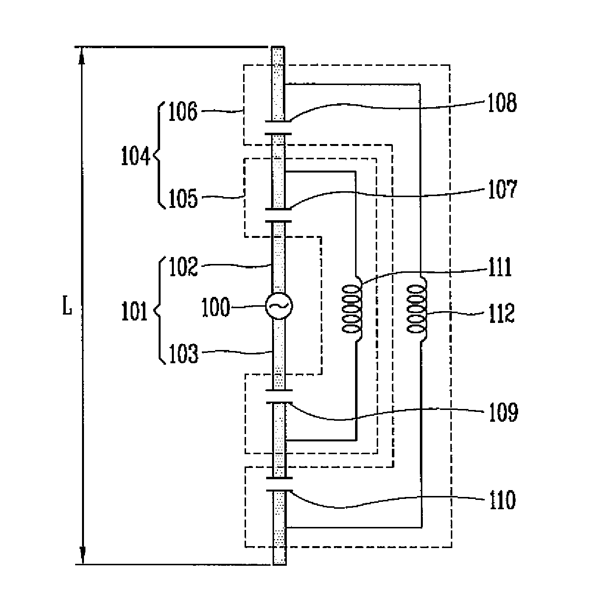
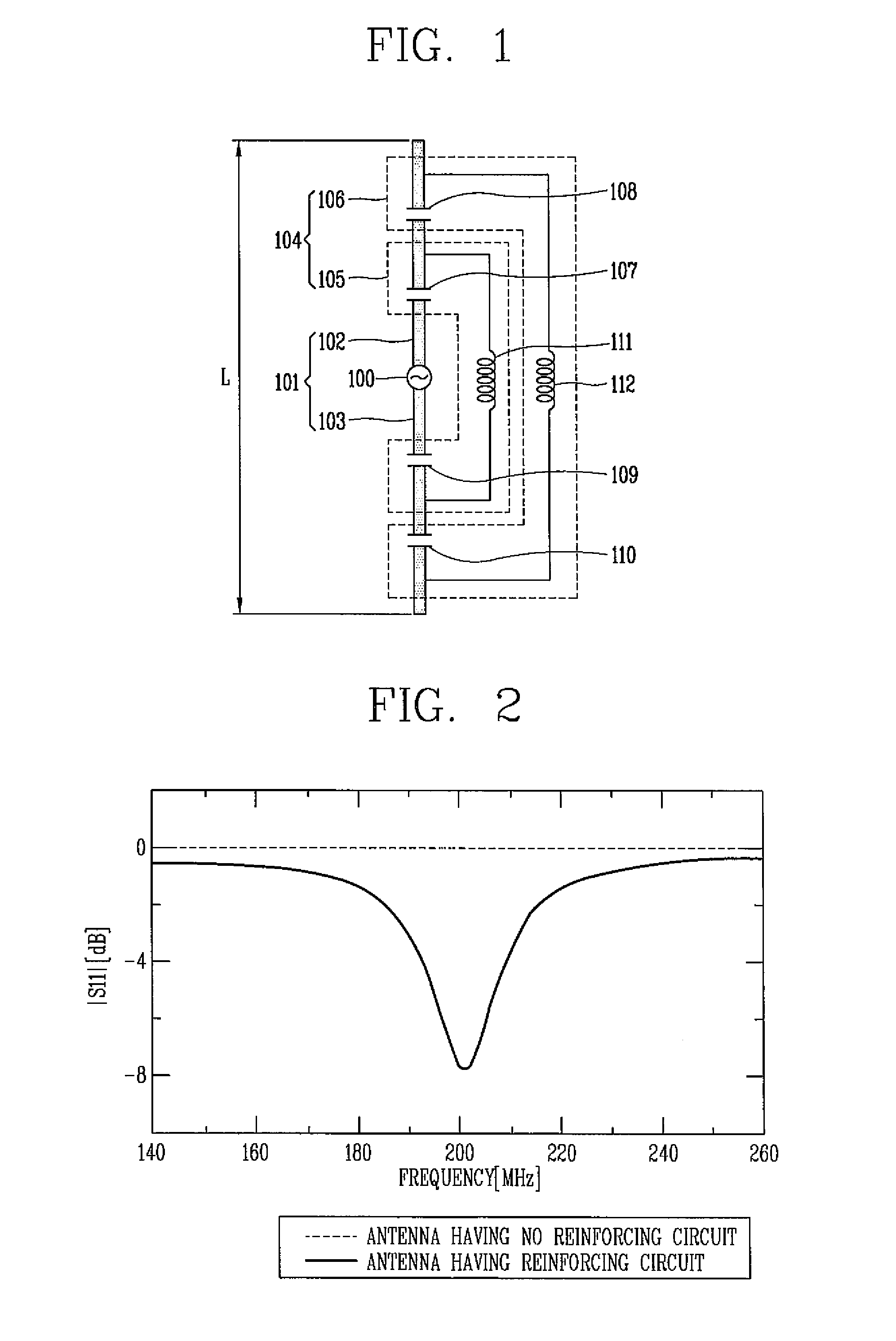
[0056]Referring to FIG. 1, the antenna according to the present invention is a dipole antenna, and comprises a radiator 101 electrically connected to a feeder 100, and one or more reinforcing circuits 104 disposed in the radiator 101 so as to uniformly distribute a current on at least one part of the radiator 101.

[0057]The radiator 101 includes first and second dipole arms 102,103 each formed of a conductive material and electrically connected to the feeder 100. Voltages (potentials) of the first and second dipole arms 102, 103 each supplied from the feeder 100 have a phase difference of approximately 180° therebetween. A total length of the first and second dipole arms 102, 103 is about 1 / 20 of a wavelength of an operation frequency. Accordingly, when the first and second dipole arms 102, 103 have no reinforcing circuit 104, a resonance does not occur near an operation frequency (200 MHz) as shown by the dotted line of FIG. 2.

[0058]The first and second dipole arms 102, 103 may be i...

second embodiment

[0079]FIG. 11 is a conceptual view schematically showing a dipole antenna according to the present invention. Referring to FIG. 11, an impedance matching unit 124 is disposed on a transmission line 123 between a feeder 120 and a radiator 121. As the impedance matching unit 124 is disposed on the transmission line 123 together with the reinforcing circuit 122, an impedance matching is optimized thus to enhance efficiency of the antenna.

third embodiment

[0080]FIG. 12 is a conceptual view schematically showing a dipole antenna according to the present invention. Referring to FIG. 12, since first and second dipole arms 132,132 are disposed in parallel to each other, connection conductors 130 for connecting inductors 133,134 to the first and second dipole arms 132,132 can have a minimized length. As the connection conductors 130 have a minimized length, the antenna has a reduced size, and an electromagnetic field interference due to the connection conductors 130 is decreased.


PUM


Abstract

An antenna and electronic equipment having the same are disclosed. The antenna comprises: a radiator electrically connected to a feeder, and radiating an electric wave; and one or more reinforcing circuits disposed in the radiator so as to uniformly distribute a current on at least one part of the radiator. The antenna can have a length much shortened than a wavelength of an operation frequency with maintaining the same efficiency, thereby being able to be mounted even in electronic equipment such as a terrestrial DMB terminal operated at a low frequency bandwidth,

Description

RELATED APPLICATION[0001]The present disclosure relates to subject matter contained in priority Korean Application No. 10-2006-0139072 filed on Dec. 29, 2006, No. 10-2006-0139073 filed on Dec. 29, 2006, and No. 10-2006-0139074 filed on Dec. 29, 2006, which are herein expressly incorporated by reference in its entirety.BACKGROUND OF THE INVENTION[0002]1. Field of the Invention[0003]The present disclosure relates to an antenna for transmitting / receiving an electric wave and electronic equipment having the same.[0004]2. Description of the Background Art[0005]Electronic equipment having communication means therein serves to reproduce received electric waves, or serves to transmit signals generated therefrom in an electric wave form. The electronic equipment includes portable phones, PDAs (Personal Digital Assistants), car navigators, notebook computers, data recording, reproducing and displaying machines, electronic dictionaries, MP3 players, MD players, radios, audio, etc.[0006]The ele...

Claims


Application Information

Patent Timeline
Patent Type & Authority Applications(United States)
IPC IPC(8): H01Q1/00H01Q9/16
CPCH01Q9/0407H01Q9/30H01Q9/16
Inventor KIM, MOON-ILLEE, KOOK-JOOKIM, HONG-TEUK
Owner LG ELECTRONICS INC
Why Eureka
Try Eureka