Extended Depth Of Field Optical Systems

a technology of optical systems and depths, applied in the direction of direction/deviation determining electromagnetic systems, instruments, reradiation, etc., can solve problems such as red light focus in a different plane, minimize the effects of misfocus aberration, and extend the depth of field of imaging systems.

Inactive Publication Date: 2008-07-24
UNIV OF COLORADO THE REGENTS OF
View PDF99 Cites 5 Cited by
  • Summary
  • Abstract
  • Description
  • Claims
  • Application Information

AI Technical Summary

Benefits of technology

[0013]An object of the present invention is to increase depth of field in an incoherent optical imaging system by adding a special purpose optical mask to the system that has been designed to make it possible for digital processing to produce an image with in-focus resolution over a large range of misfocus by digitally processing the resulting intermediate image. The mask causes the optical transfer function to remain essentially constant within some range away from the in-focus position. The digital processing undoes the optical transfer function modifying effects of the mask, resulting in the high resolution of an in-focus image over an increased depth of field.
[0018]A third object of this invention is to extend the band of wavelengths (colors) that form an in-focus image. By extending the depth of field of the system, the regions are extended where each wavelength forms an in-focus image. These regions can be made to overlap and the system, after digital processing, can produce a high resolution image at the three different color bands.
[0020]A fifth object of this invention is to extend the depth of field of imaging system s to minimize the effects of misfocus aberrations like spherical aberration, astigmatism, and field curvature. By extending the depth of field the misfocus aberration s can have overlapping regions of best focus. After digital processing, can produce images that minimize the effects of the misfocus aberrations.
[0021]A sixth object of this invention is to physically join the mask for extending depth of field with other optical elements, in order to increase the depth of field of the imaging system without adding another optical element.

Problems solved by technology

A drawback of simple optical systems is that the images formed with red light focus in a different plane from the images formed with blue or green light.
There are several other aberrations that result in misfocus.

Method used


Image

  • Extended Depth Of Field Optical Systems
  • Extended Depth Of Field Optical Systems
  • Extended Depth Of Field Optical Systems

Examples


Embodiment Construction

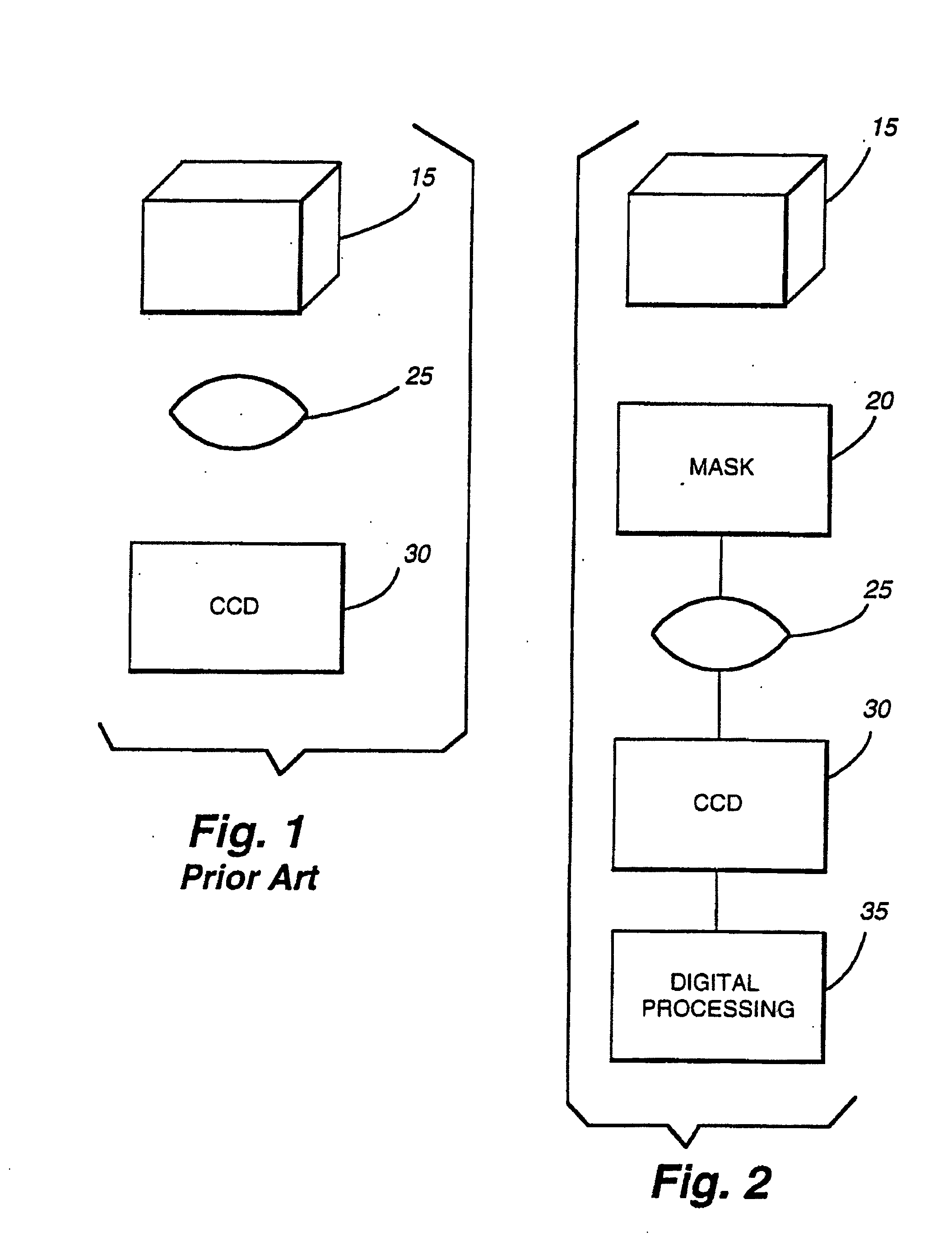
[0072]FIG. 1 (prior art) shows a standard optical imaging system. Object 15 is imaged through lens 25 onto Charge Coupled Device (CCD) 30. Such a system creates a sharp, in-focus image at CCD 30 only if object 15 is located at or very close to the in-focus object plane. If the distance from the back principal plane of lens 25 to CCD 30 is di, and focal length of lens 25 is f, the distance, d0, from the front principal plane of lens 25 to object 15 must be chosen such that:

1do+1di-1f=0

in order for the image at CCD 30 to be in-focus. The depth of field of an optical system is the distance the object can move away from the in-focus distance and still have the image be in focus. For a simple system like FIG. 1, the depth of field is very small.

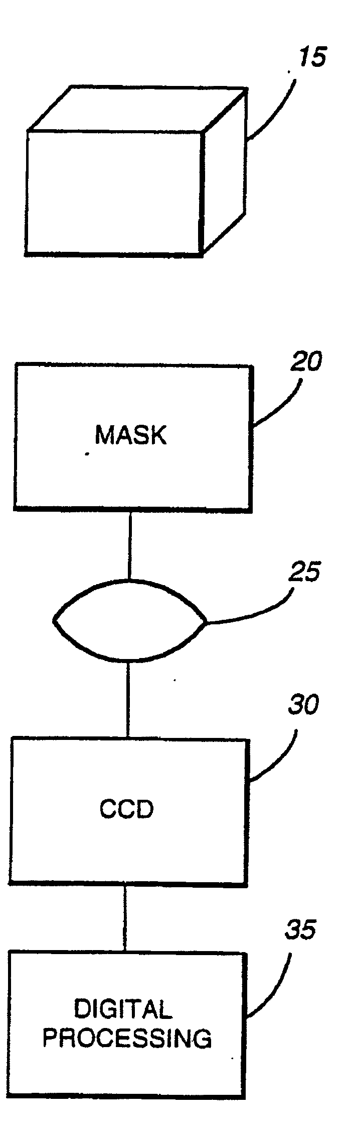
[0073]FIG. 2 shows the interaction and operation of a multi-component extended depth of field system in accordance with the invention. Object 15 is imaged through optical mask 20 and lens 25 onto Charge Coupled Device (CCD) system 30, and image po...


PUM


Abstract

An imaging system is characterized at least by an ambiguity function (“AF”) and a point spread function (“PSF”). The AF is a function of parameters u and v related to a misfocus parameter ψ; the PSF is at least a function of ψ. The system includes (1) an image recording device, (2) an optical arrangement for imaging an object to the image recording device, and (3) a post processor that renders an in-focus electronic image over a range of distances between the object and the optical arrangement. The optical arrangement alters phase such that a main lobe of the AF is broader in v for a specific u. The PSF has a functionally different form for a specific ψ, in comparison to a PSF characterizing the system when the optical arrangement does not alter the phase for those specific values of u and ψ over the range of distances.

Description

RELATED APPLICATIONS[0001]This application is a continuation of commonly owned and copending U.S. patent application Ser. No. 09 / 070,969, filed on May 1, 1998, which is a continuation-in-part of U.S. patent application Ser. No. 08 / 823,894 filed on Mar. 17, 1997, now U.S. Pat. No. 5,748,371, which is a continuation of application Ser. No. 08 / 384,257, filed Feb. 3, 1995, now abandoned. U.S. Pat. No. 5,521,695, issued May 28, 1996 and entitled “Range Estimation Apparatus and Method,” is incorporated herein by reference.STATEMENT REGARDING FEDERALLY SPONSORED RESEARCH OR DEVELOPMENT[0002]This invention was made with Government support awarded by the National Science Foundation and the Office of Naval Research. The Government has certain rights in this invention.BACKGROUND OF THE INVENTION[0003]1. Field of the Invention[0004]This invention relates to apparatus and methods for increasing the depth of field and decreasing the wavelength sensitivity of incoherent optical systems. This inven...

Claims


Application Information

Patent Timeline
Patent Type & Authority Applications(United States)
IPC IPC(8): G02B5/18G01S3/783G02B5/00G02B27/00G02B27/46
CPCG01S3/7835G01S11/12G02B5/00G02B7/365G02B27/52G02B21/14G02B27/0025G02B27/46G02B7/40
Inventor CATHEY, WADE THOMASDOWSKI, EDWARD R.
Owner UNIV OF COLORADO THE REGENTS OF
Why Eureka
Try Eureka