Eureka AIR delivers breakthrough ideas for toughest innovation challenges, trusted by R&D personnel around the world.

Methods and systems for remediating contaminated soil

Inactive Publication Date: 2008-07-24
MECO ENVIRONMENTAL
View PDF20 Cites 7 Cited by
  • Summary
  • Abstract
  • Description
  • Claims
  • Application Information

AI Technical Summary

Benefits of technology

[0012]The subject invention is not a closed loop system as indicated in U.S. Pat. Nos. 5,213,445 and 5,067,832. The system and method of this invention also does not make use of a vacuum to encourage contaminants to achieve vapor phase. The system and method herein are designed to treat both volatile and semi-volatile contaminants as well as a wide variety of soil types (frozen, very wet, high clay content, etc.) Unlike the prior art systems and methods, in the process and method of this invention, soil can be packed down without decreasing the efficiency of the system. Moreover, the system and method described herein allows the ability to re-circulate the vapors generated during breakdown of contaminants allowing for use of the re-circulated vapor for heat production and energy use. Still further, the system and method described herein allows for portability and use of the system in remote locations whereby the system does not require use of a container or receptacle.
[0020]More specifically, flow channels are provided which extend though the multi-functional conduits for removing the contaminated vapor from within the soil remediation cell. Preferably, this function is accomplished by conductively heating the contaminated soil with the high temperature heat, thereby volatilizing the contaminants located within the contaminated soil and producing a pressurized, contaminated vapor. Preferably, perforations provided in the multi-functional conduits act as flow channels allowing the contaminated vapors to migrate from the contaminated soil, through the perforations, and into and through the multi-functional conduits. The contaminated vapors typically move from the contaminated soil, where the vapors are under high pressure, through the perforations in, for example, multi-functional manifolds, and into the multi-functional conduits which are maintained at low pressure. The movement of the contaminated vapors is therefore preferably due to the pressure differential between the high-pressure soil and the low-pressure conduits. By removing the contaminated vapor from within the soil remediation cell through the multi-functional conduits, the contaminants are expurgated from the contaminated soil. However, an additional advantage is to use the contaminated vapor as an energy source. The vapor produced by the system may be utilized and re-circulated through the system to be utilized to facilitate the heating elements. The vapor which is usually in a heightened temperature may re-circulate and used by the heating elements to keep the contaminated soil at a higher temperature point, thereby diminishing and / or eliminating the additional power necessary to fuel the heating elements.
[0026]The heat for destroying the contaminants in the contaminated soil is typically produced by an electrical current. Typically, this heat is infrared heat. However, in an exemplary embodiment of the present invention, the heat may be generated from both electric current and from the re-circulation of the vapors from the contaminated soils. In an exemplary embodiment, the vapors may be presented with a reactive portion whereby when energized, the vapor may be converted into additional heat, thereby reducing the amount of electrical current and / or gas needed to produce the necessary heat.

Problems solved by technology

The air flows from the distribution pipes, through the contaminated soil, and volatilizes contaminants within the contaminated soil.
Recirculation of air through heaters reduces oxygen in the air stream thereby reducing the effective level of volatilization.
These systems of U.S. '852, U.S. '445 and U.S. '236 make use of a vacuum to encourage contaminants to achieve vapor phase which has proven to be an ineffective approach for affecting remediation.
Therefore, the soil cannot be packed down to maintain the structural integrity of the soil stack without adversely affecting the efficiency of the remediation process.
This results in the migration of volatilized contaminants and moisture through the perforations in the pipe walls and into the lower pressure area within the heated steel pipes, forcing the contaminants from the soil and into an off-gas treatment system.
The forced air system described in U.S. Pat. No. 6,000,822 generates a substantial volume of heated air which is a burden on capacity and operability of the subject contaminant removal system.

Method used


Image

  • Methods and systems for remediating contaminated soil
  • Methods and systems for remediating contaminated soil
  • Methods and systems for remediating contaminated soil

Examples


Embodiment Construction

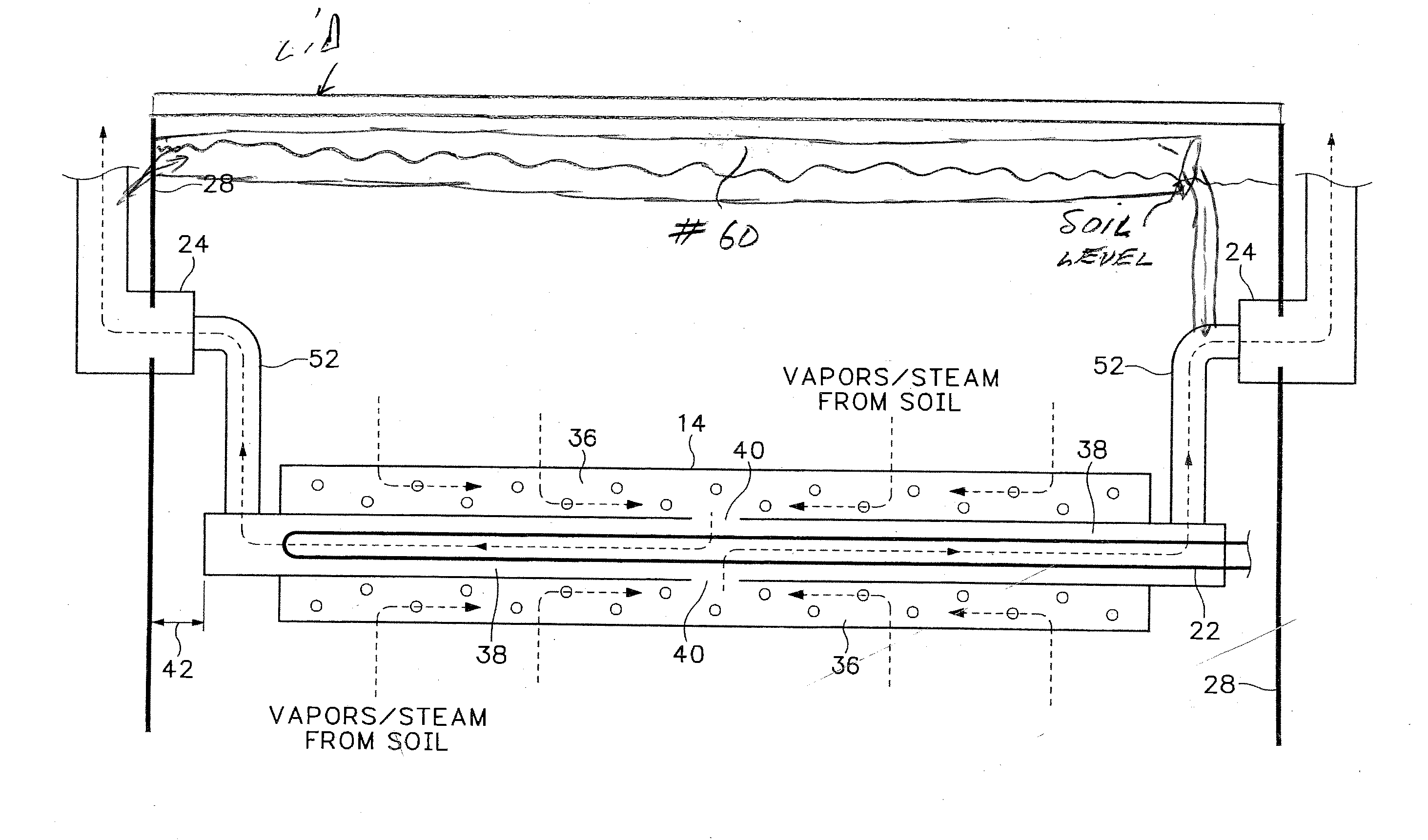
[0037]Referring to FIGS. 1-4, systems 1 and 1a are provided for remediation of contaminated soil which is removed from or stored at a contaminated soil remediation site.

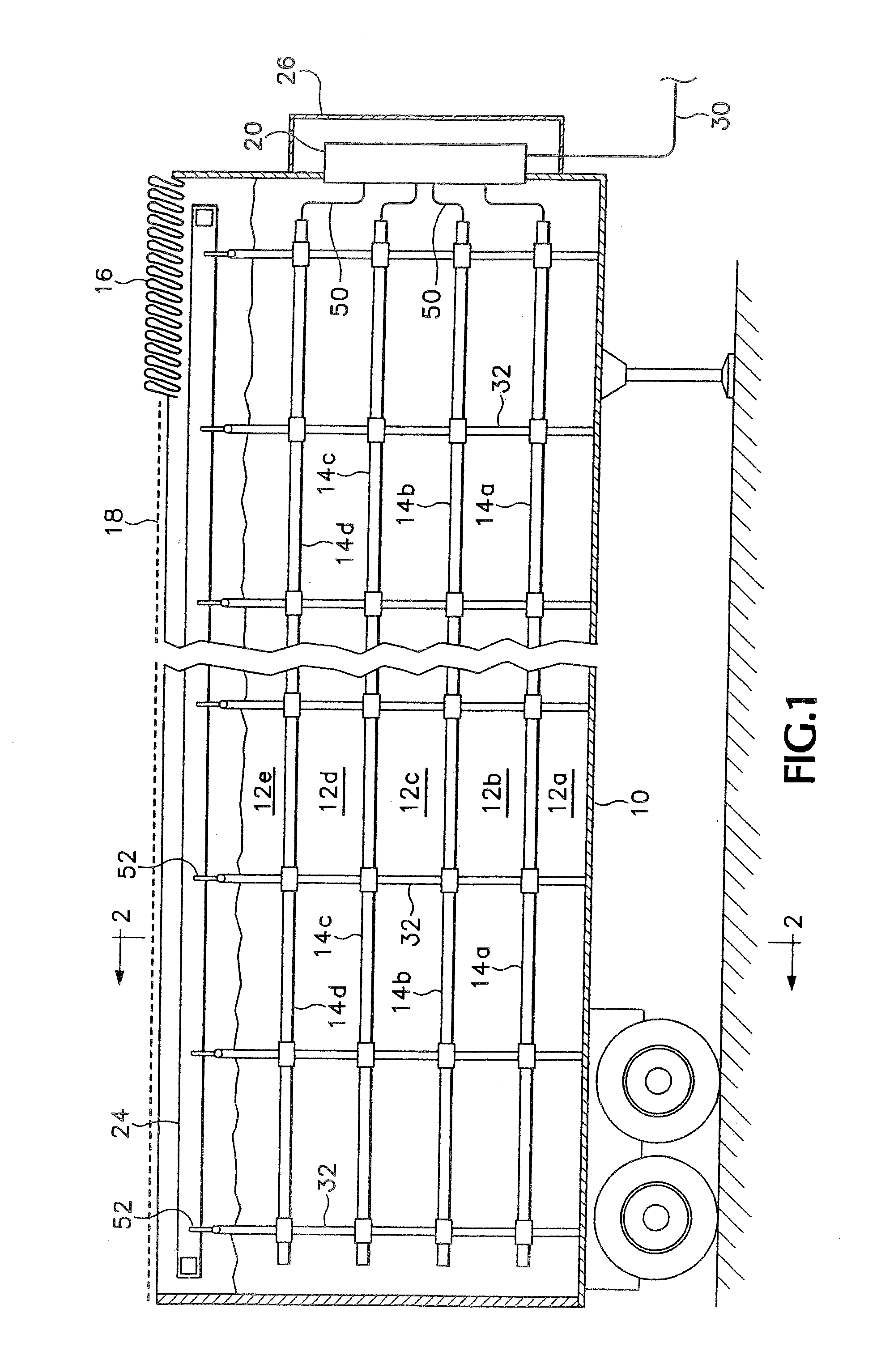
[0038]Referring to FIGS. 1 and 2, the system 1 of the present invention can comprise a multi-layer contaminated soil remediation cell formed of a plurality of adjacent layers of contaminated soil 12a-12e, having a plurality of multi-functional conduits 14a-14d located between the adjacent layers of contaminated soil, all housed within a structural enclosure 10, which in this case comprises a transportable trailer. The multi-functional conduits 14a-14d are supported by conduit supports 32. The conduit supports 32 also function as a vapor path from the multi-functional conduits 14a-14d to the exhaust manifold 24.

[0039]In order to prepare for use of one of these remediation cells, a 20 ft×40 ft work area is cleared and leveled. This work area can comprise concrete, soil, asphalt or any other surface that can support the...


PUM


Abstract

A system and method for remediation of contaminated soil are provided. The system comprises a soil remediation cell of contaminated soil and a plurality of multi-functional conduits located within the contaminated soil. Each multi-functional conduit defines a reaction housing. The multi-functional conduits includes heating elements for introducing heat into the contaminated soil for volatilizing the contaminants located within the contaminated soil, without utilizing mechanically driven forced air. This produces a contaminated vapor. The system and allows for re-circulation of vapors generated during breakdown of contaminants allowing for use of the re-circulated vapor for heat production and energy use. The system may be utilized for remote access and portability to disparate locations whereby the system does not require use of a container or receptacle. A substantial portion of the contaminants in the contaminated vapor are destroyed in the reaction housing. A substantially non-contaminated vapor is produced in which at least about 80% by weight of the contaminants have been destroyed.

Description

RELATED APPLICATION[0001]This application is a continuation-in-part of pending U.S. patent application Ser. No. 10 / 535,612 filed on Jan. 13, 2006, and a national stage enter under 35 USC 371 of PCT / US03 / 38839 filed on Dec. 5, 2003, that claims priority back to U.S. Provisional Application No. 60 / 431,388 filed on Dec. 5, 2002, which is hereby incorporated by reference in it entirety.BACKGROUND OF THE INVENTION[0002]The invention relates to methods and systems for remediating contaminated soil, and more particularly to methods and systems for volatilizing contaminants in the soil and effectively and efficiently destroying the same therefrom. Systems for conducting fluids through a soil stack are also known. U.S. Pat. No. 4,139,321 describes a rock channel heat storage method involving conduit connections provided within a rock-filled channel. The conduits are used to conduct fluid through the rock pile to either absorb or disperse thermal energy. Soviet Patent 837,997 describes a meth...

Claims


Application Information

Patent Timeline
IPC IPC(8): B09C1/06
CPCB09C1/06
Inventor RICHTER, ROGER T.
Owner MECO ENVIRONMENTAL
Why Eureka
Eureka Blog
Learn More