Cooling apparatus for an electronic device to be cooled

a technology for cooling apparatus and electronic devices, which is applied in the direction of magnetic circuit rotating parts, piston pumps, magnetic circuit shapes/forms/construction, etc., can solve the problems of inefficient cooling effect of cooling units according to us2006/0021735a1, drawing a limited amount, and general inefficiency of radial flux machines, etc., to achieve compact construction, increase flow rate, and optimize airflow

Active Publication Date: 2008-07-24
MINEBEAMITSUMI INC
View PDF3 Cites 17 Cited by
  • Summary
  • Abstract
  • Description
  • Claims
  • Application Information

AI Technical Summary

Benefits of technology

[0010]In a preferred embodiment, the heat exchange elements are designed as cooling fins that are connected to the hub. The cooling fins are preferably curved such that they follow the swirl of air produced by the impeller when the impeller is in operation. The impeller itself preferably has fan blades that are curved in the opposite direction to the cooling fins of the heatsink. In the cooling apparatus according to the invention, the airflow enters in an axial direction at the center of the impeller, on the side lying opposite to the baseplate, and is exhausted towards the outside in a radial direction by the impeller. The design of the hub, the cooling fins and the fan blades makes it possible to optimize the airflow, i.e. to maximize it in relation to the volume of the cooling apparatus and the rotational speed.
[0011]In a preferred embodiment of the invention, the impeller is journaled within the hub via a shaft. It has an impeller ring that is connected to the shaft via spokes. In a particularly advantageous embodiment of the invention, the spokes are designed such that they extend obliquely in an axial direction or are chamfered in order to generate an axial airflow component in addition to the radial airflow and to thus additionally increase the flow rate through the cooling apparatus.
[0012]The drive motor of the cooling apparatus according to the invention comprises a stator and a rotor. The stator is preferably connected to the hub and the rotor is connected to the impeller, the rotor coaxially enclosing the stator. The drive motor is thus realized as a radial flux machine having an external rotor configuration. The stator has a stator stack having stator poles and stator coils mounted on the stator poles. The rotor has a ring magnet or a plurality of single permanent magnets that are coupled to an annular back yoke. The back yoke is preferably integrated in the impeller so as to achieve the most compact construction possible.
[0013]For the same overall volume, using a radial flux machine rather than a motor with disk-shaped rotor means greater efficiency, with no restriction to the coil current and the number of coil windings. The stator stack according to the invention may be made extremely flat, built up, for example, of only 3 or 4 thin stator laminations and wound from the outside in a conventional manner. The heatsink may be substantially disposed above the stator stack as well as between the stator poles, so as to make optimal use of the space available. The rotor is integrated in the impeller and thus has almost no additional space requirement. Since the stator is disposed below the heatsink and the rotor radially outside it, these parts do not obstruct the flow of air through the heatsink.

Problems solved by technology

However, the use of motors with disk-shaped rotors has the disadvantage that the flat coils used for the stator are restricted with respect to the number of their windings and they can only draw a limited amount of current, making them generally less efficient than radial flux machines.
In addition, the cooling effect of the cooling unit according to US2006 / 0021735A1 is not optimal due to the construction of the heatsink and the almost total inclusion of the heatsink in a housing, where only one outlet is open.
The hub member is relatively voluminous so that only limited space is available for the airflow.
The arrangement according to this document seems to be relatively voluminous, so that in relation to its volume, low efficiency is to be expected.
Along with the reduction in size of electronic components and the increase in their performance, there is a rise in the amount of heat generated.
Furthermore, modern processors may have increased power consumption and also increasingly efficient electronic power components are being launched on the market.

Method used


Image

  • Cooling apparatus for an electronic device to be cooled
  • Cooling apparatus for an electronic device to be cooled
  • Cooling apparatus for an electronic device to be cooled

Examples


Embodiment Construction

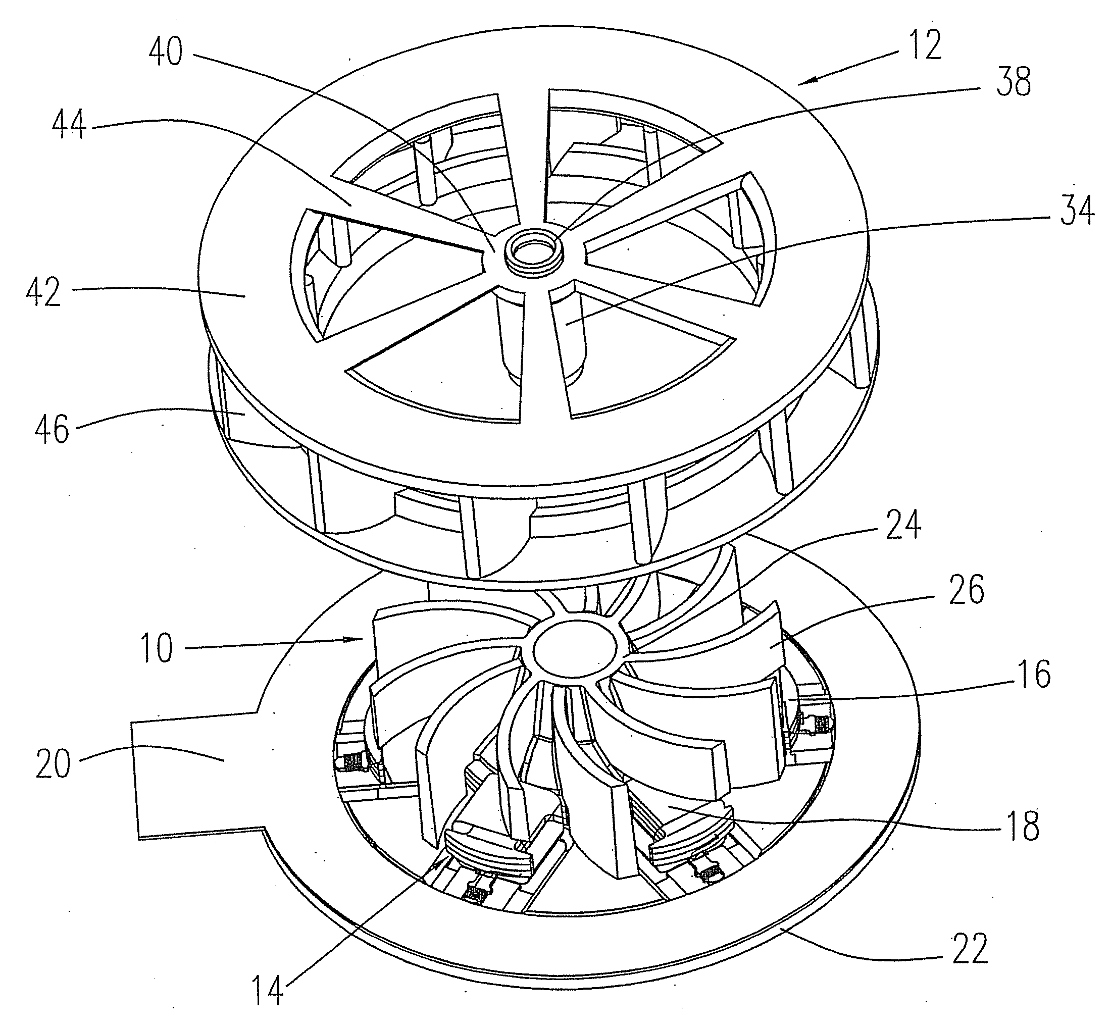
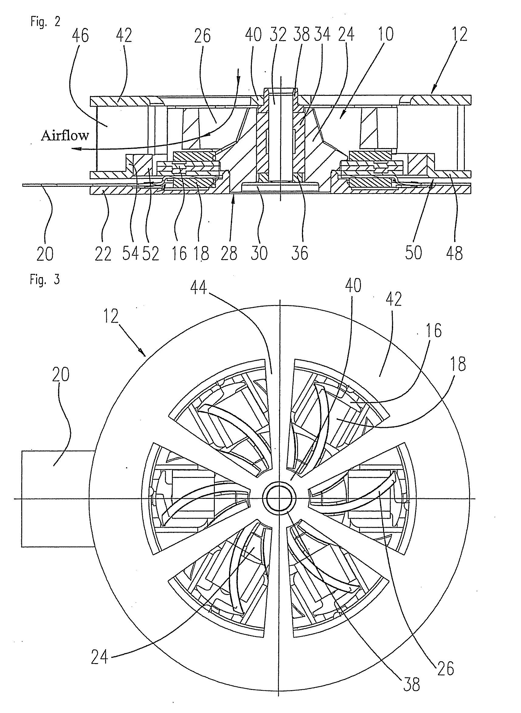
[0021]FIGS. 1 to 3 show a preferred embodiment of a cooling apparatus according 1-5 to the invention. The cooling apparatus comprises a heatsink 10, an impeller 12 and a drive motor 14 of which only the stator 16 is illustrated in FIG. 1. In the illustrated embodiment, the stator 16 is represented by a stator stack or lamination stack having six poles on which stator coils 18 are mounted. The terminals of the stator coils 18 are connected to a circuit board 20 that may also carry sensors to measure the position of the rotor or the heat of the baseplate.

[0022]The stator 16 is seated on a baseplate 22 into which the heatsink 10 is inserted. The heatsink 10 comprises a hub 24 and cooling fins 26 that are curved like fan blades such that on rotation of the impeller 12 they follow the swirl of air produced by the impeller. In the illustrated embodiment, the hub 24 of the heatsink 10 takes the form of two cones placed one on top of the other so as to form the largest possible base 28. In ...


PUM


Abstract

The invention relates to a cooling apparatus for an electric component such as a CPU, a memory or power semiconductor, such as transistors or LEDs, or a processor. The cooling apparatus comprises a heatsink, an impeller that coaxially encloses the heatsink, and
  • a drive motor for the impeller. The heatsink takes the form of a stationary hub having a base for introducing heat from the electronic component that is to be cooled, the hub widening towards the base. Cooling fins are thermally coupled to the hub, the cooling fins being given a spiral-like curve similar to the blades of the impeller. Due to the special design of the hub and the cooling fins as well as the use of a radial flux motor, a highly efficient, particularly compact cooling apparatus can be realized.

Description

FIELD OF THE INVENTION[0001]The invention relates to a cooling apparatus for an electronic device to be cooled including a heatsink.BACKGROUND OF THE INVENTION[0002]US 2006 / 0021735 A1 describes a cooling unit in which a heatsink is integrated in a radial blower. The heatsink comprises a base and heat exchanging means talking the form of spiral cooling fins or cooling pins. The impeller surrounds the heatsink coaxially. A drive motor is designed as a motor with disk-shaped rotor, the rotor being integrated in the impeller and an annular arrangement of stator coils lying opposite to the rotor in an axial direction. The impeller has a large central opening, the stream of air flowing through this central opening in an axial direction towards the cooling fins of the heatsink and from there being conducted in a radial direction over the blades of the impeller and through a lateral outlet. According to this document, it is advantageous to use a motor with disk-shaped rotor rather than a ra...

Claims


Application Information

Patent Timeline
Patent Type & Authority Applications(United States)
IPC IPC(8): F04B17/03
CPCF04D25/0613F04D29/582F04D29/542F04D29/544
Inventor WYSK, HANS-JOACHIMGLATZ, KARL-HEINZ
Owner MINEBEAMITSUMI INC
Why Eureka
Try Eureka