Methods and systems for reducing NOx emissions in industrial combustion systems

Inactive Publication Date: 2008-07-24
GENERAL ELECTRIC CO
View PDF14 Cites 19 Cited by
  • Summary
  • Abstract
  • Description
  • Claims
  • Application Information

AI Technical Summary

Benefits of technology

[0008]In one aspect, a method for operating a combustion system to facilitate reducing emissions from the system is provided. The method includes supplying an aqueous selective reducing agent from an aqueous selective reducing agent source to an atomizer that is directly coupled in flow communication with the aqueous selective reducing agent source. The method also includes atomizing the selective reducing agent in the atomizer, and injecting atomized droplets of the selective reducing agent from the atomizer directly into a transport stream of flue gas flowing within a temperature zone defined within the combustion system.
[0009]In another aspect, a combus

Problems solved by technology

However, generally pre-combustion technologies may be limited in reducing NOx emissions because air containing N2 is used to burn the low nitrogen fuel, and as such, oxidation of the N2 in the air may occur during combustion to form additional NOx emissions.
However, generally combustion modification control technologies include limited NOx emissions reduction, stringent operating tolerances, and limited residence times to complete combustion.
Although the SCR system significantly reduces NOx more efficiently than known combustion modification control technologies, known SCR systems require a large catalyst bed, large amounts of catalysts, and catalysts disposal systems, all of which may be more difficult and more expensive to operate than combustion

Method used


Image

  • Methods and systems for reducing NOx emissions in industrial combustion systems
  • Methods and systems for reducing NOx emissions in industrial combustion systems
  • Methods and systems for reducing NOx emissions in industrial combustion systems

Examples


Embodiment Construction

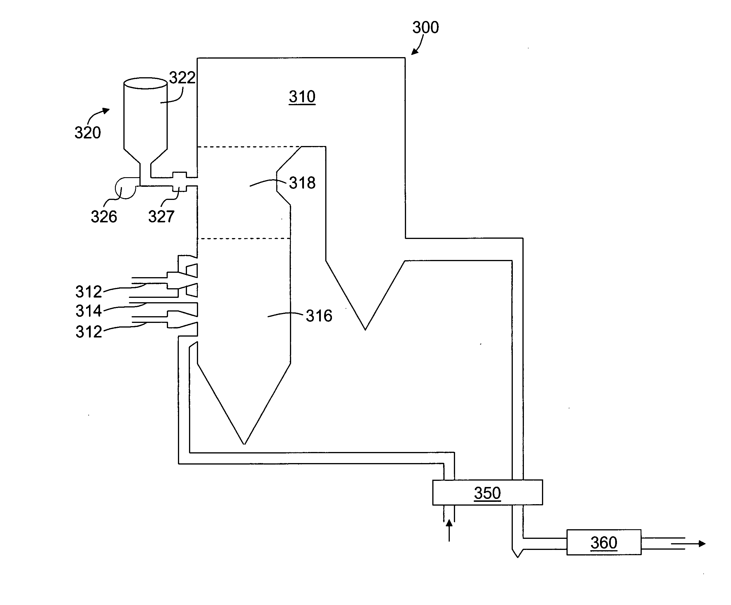
[0015]The exemplary methods and systems described herein overcome the structural disadvantages of known Selective Catalytic Reduction (SCR) and Selective Non-Catalytic Reduction (SNCR) systems by reducing the number of components coupled within each respective system.

[0016]It should be appreciated that the term “SCR system” is used throughout this application to refer to a combustion system implementing a Selective Catalytic Reduction (SCR) control technology that injects a reagent to facilitate selectively reducing nitrogen oxides (“NOx”) emissions.

[0017]It should be appreciated that the term “SNCR system” is used throughout this application to refer to a combustion system implementing a Selective Non-Catalytic Reduction (SNCR) control technology that injects a reagent to facilitate selectively reducing NOx emissions.

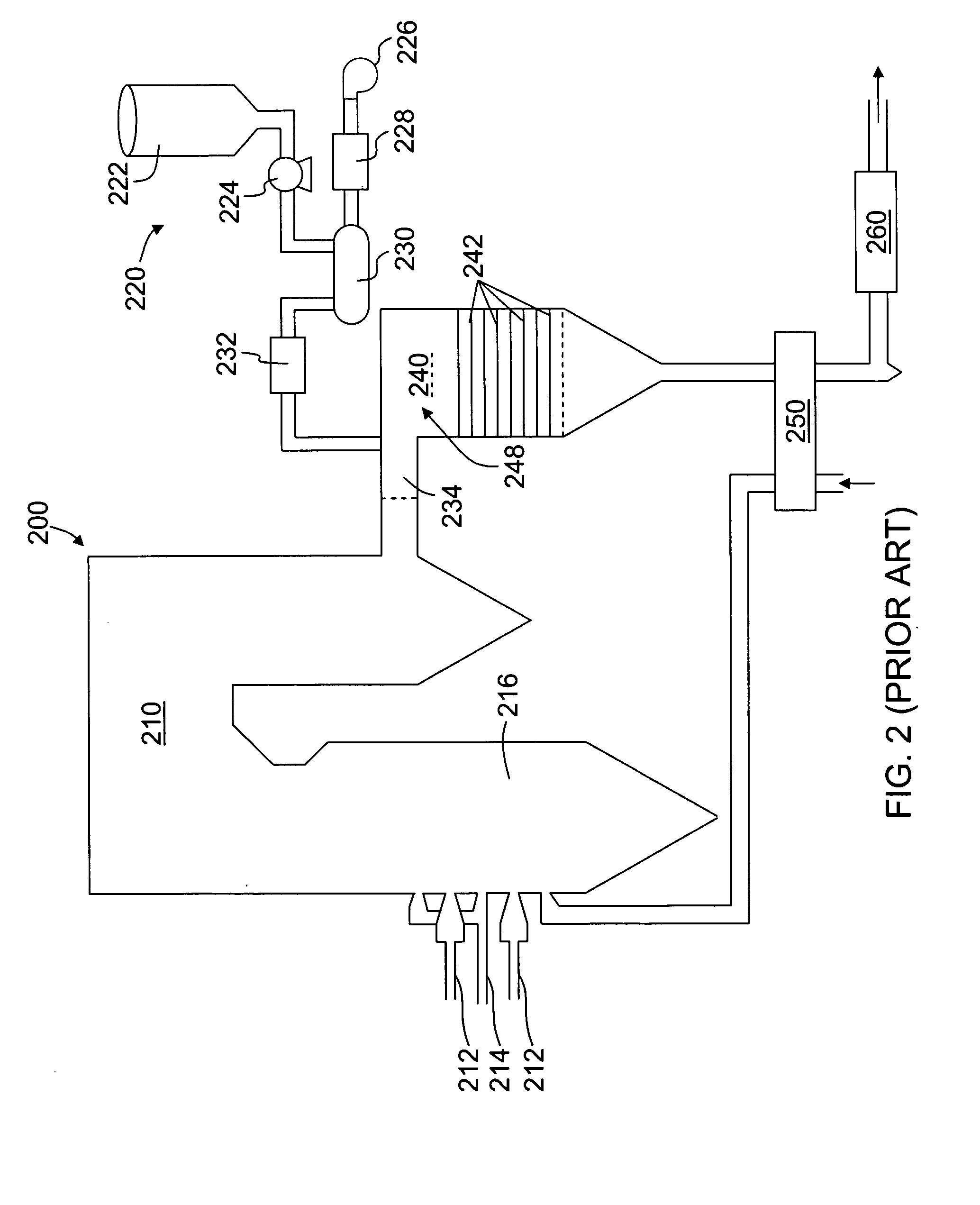
[0018]FIG. 1 illustrates a schematic diagram of a known SNCR system 100. In the exemplary embodiment, SNCR system 100 includes a furnace / boiler 110, a reagent injectio...


PUM

PropertyMeasurementUnit
Temperatureaaaaaaaaaa

Abstract

A method for operating a combustion system to facilitate reducing emissions from the system is provided. The method includes supplying an aqueous selective reducing agent from an aqueous selective reducing agent source to an atomizer that is directly coupled in flow communication with the aqueous selective reducing agent source. The method also includes atomizing the selective reducing agent in the atomizer, and injecting atomized droplets of the selective reducing agent from the atomizer directly into a transport stream of flue gas flowing within a temperature zone defined within the combustion system.

Description

BACKGROUND OF THE INVENTION[0001]This invention relates generally to industrial combustion systems, and more particularly to methods and systems for reducing NOx in industrial combustion systems.[0002]During the combustion of natural gas and pulverized coal, nitrogen oxides (“NOx”) emissions are formed by the oxidation of nitrogen in combustion air that is under high temperatures. At least some known NOx emission sources include devices such as, but not limited to, industrial boilers and furnaces, larger utility boilers and furnaces, gas turbine engines, steam generators, and other combustion systems. Because of stringent emission control standards, it is desirable to control NOx emissions by either suppressing NOx formation and / or by reducing NOx to molecular nitrogen (“N2”) and water (“H2O”).[0003]At least some known combustion systems attempt to reduce NOx emissions from a furnace / boiler in at least the following stages: (1) before combustion—using pre-combustion control technolo...

Claims


Application Information

Patent Timeline
IPC IPC(8): B01D53/38
CPCB01D53/56B01D53/79B01D53/8625F23J2219/10F23J7/00F23J15/003F23J2215/10B01D53/90B01D53/76F01N3/206
Inventor MORRISON, DONALD KEITHLIPINSKI, WILLIAM THEODOREHARTSOCK, DONALD KEITH
Owner GENERAL ELECTRIC CO
Why Eureka
Try Eureka