

Sheet member, forming method of the same, exhaust gas treatment apparatus, and muffling apparatus
a technology of sheet member and muffling device, which is applied in the direction of machine/engine, record information storage, packaging, etc., can solve the problems of human health, affecting the working environment, and difficult to handle such fibers, so as to reduce the decrease of holding power, improve the working environment of handling the sheet member, and facilitate the handling of the sheet member
- Summary
- Abstract
- Description
- Claims
- Application Information
AI Technical Summary
Benefits of technology
Problems solved by technology
Method used
Image

Examples
first embodiment
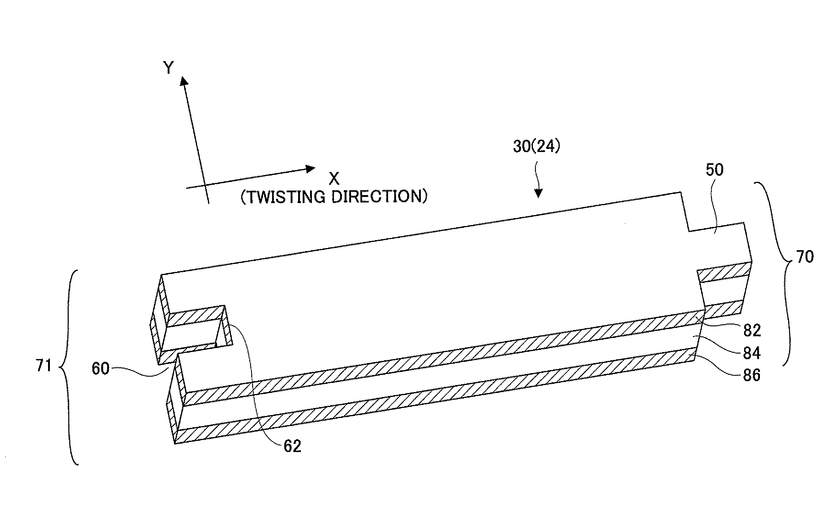
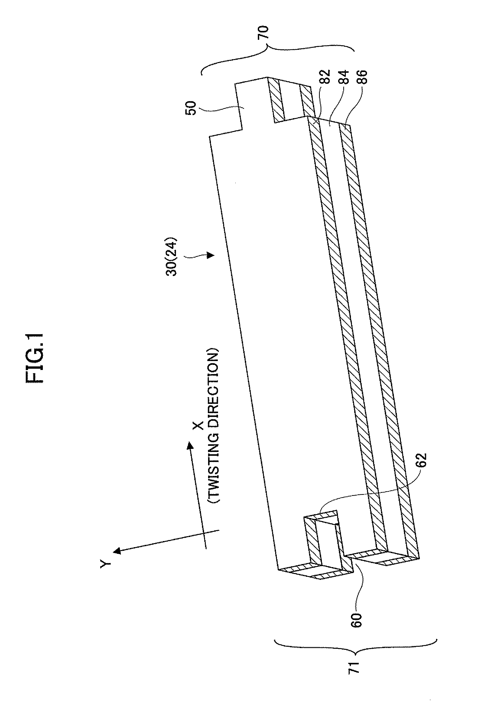
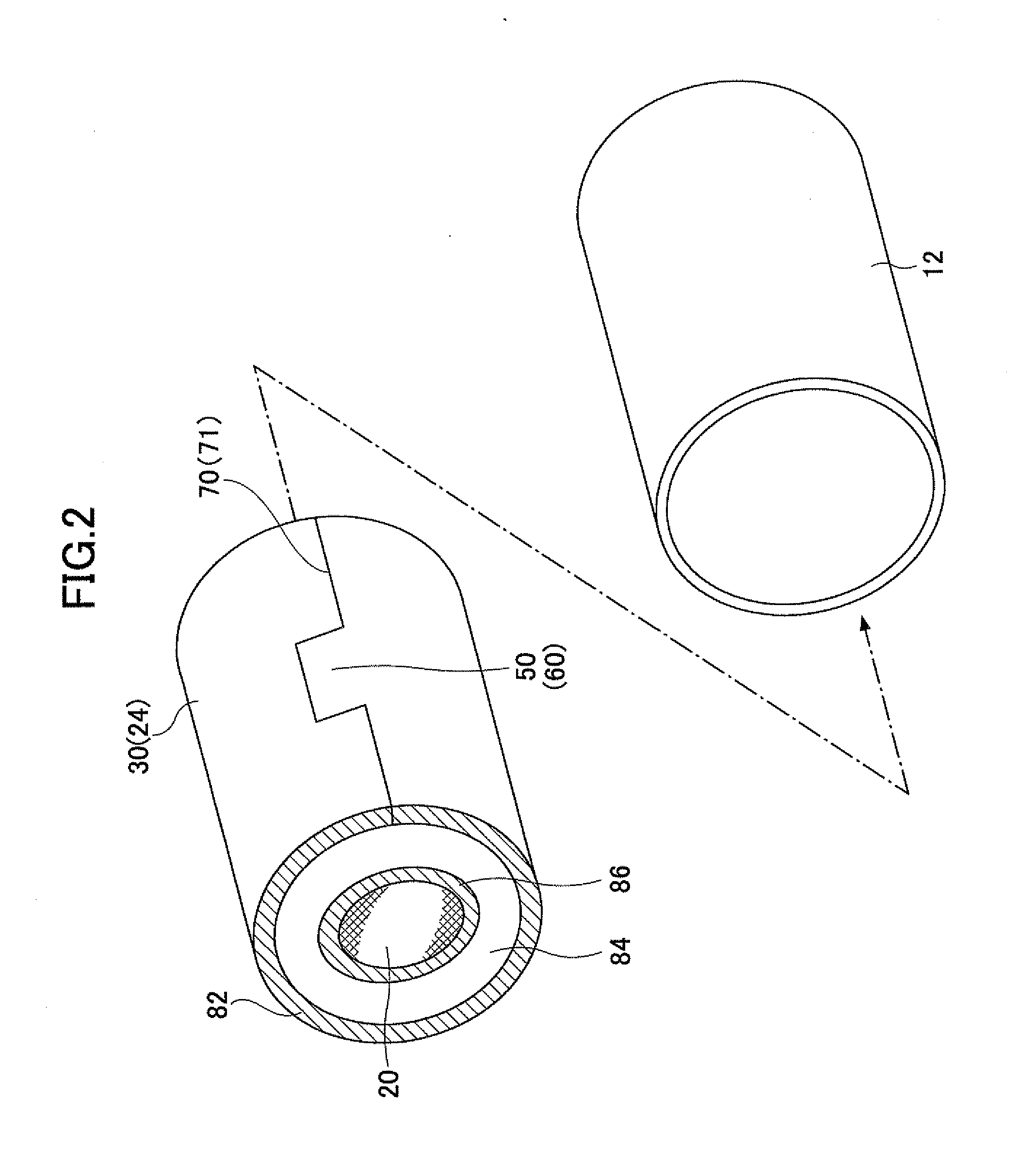
[0057]FIG. 1 shows an exemplary figure of a sheet member (a first sheet member) according to a first embodiment of the present invention. However, it should be noted that the figure of the sheet member according to an embodiment of the present invention is not limited to the figure of the sheet member shown in FIG. 1. FIG. 2 is an exploded perspective view of an exhaust gas treatment apparatus using the sheet member according to one embodiment of the present invention as a holding and sealing member of the exhaust gas treatment apparatus.
[0058]When a sheet member 30 according to an embodiment of the present invention is twisted around an exhaust gas treatment member 20 such as a catalyst carrier to be used as a holding and sealing member 24 of an exhaust gas treatment apparatus, as shown in FIG. 1, an engagement convex part 50 and an engagement concave part 60 are provided on end faces 70 and 71, respectively, perpendicular to the twisting direction (X direction) of the sheet member...
second embodiment
[0076]Next, a configuration of another sheet member (a second sheet member) according to an embodiment of the present invention is described.
[0077]Like a sheet member 30 shown in FIG. 1, the second sheet member includes the first outer layer, the center layer, and the second outer layer, those layers laminated in this order. However, in the second sheet, a value “A”, calculated by the following formula (1), of the inorganic fibers included in the first and the second outer layers is greater than approximately 6 micrometers.
A=(M−2*e) (1)
[0078]Where, a reference symbol “M” represents an average diameter of the inorganic fibers included in the outer layers. A reference symbol “e” represents a standard error given by the following formula
e=(σ÷√{square root over (n)}) (2)
[0079]Where, reference symbols “σ” and “n” represent the standard deviation and the number of measurements, respectively.
[0080]According to EU directive 97 / 69 / EC, effective on 5 Dec. 1997, the regulations for the hea...
third embodiment
[0083]In the sheet member according to the first and the second embodiments of the present invention, the minimum diameter of the inorganic fibers in the first and the second outer layers exceeds approximately 3.0 micrometers and the inorganic fibers whose value “A” in the formula (1) exceeds approximately 6 micrometers are included in the first and the second outer layers. On the other hand, in a sheet member according to the third embodiment of the present invention (a third sheet member), “bio-soluble inorganic fibers” are included in the first outer layer and / or the second outer layer.
[0084]The “bio-soluble inorganic fibers” generically refers to the inorganic fibers that satisfy so-called “Note-Q” requirements and that are not subject to control as inorganic fibers based on the “EU directive”. It should be noted that according to the “Note-Q” standards of the “EU directive”, the inorganic fibers fulfilling one of the following conditions is not classified as a control subject:[...
PUM
| Property | Measurement | Unit |
|---|---|---|
| Length | aaaaa | aaaaa |
| Length | aaaaa | aaaaa |
| Fraction | aaaaa | aaaaa |
Abstract
Description
Claims
Application Information