

Diptube apparatus and method for delivering vapor phase reagent to a deposition chamber
a technology of vapor phase reagent and deposition chamber, which is applied in the direction of container discharging methods, laboratory glassware, instruments, etc., can solve the problems of more difficult sealing and reuse, two-part containers, and more difficult cleaning than two-part containers, so as to increase the usage rate of liquid or solid precursor chemicals, reduce waste, and facilitate cleaning
- Summary
- Abstract
- Description
- Claims
- Application Information
AI Technical Summary
Benefits of technology
Problems solved by technology
Method used
Image

Examples
example 1
Preparation of Top Wall Member and Protuberance Surfaces
[0302]As depicted in FIG. 5, the opposing sealing surfaces of the top wall member and the protuberance incorporate Stellite and can cover the full width of the top wall member and protuberance sealing areas. The sealing surfaces are then polished to a finish of 10-100 RMS, preferable 15 RMS.
example 2
Preparation of Top Wall Member and Protuberance Surfaces
[0303]In this example, the opposing sealing surfaces of the top wall member and the protuberance are polished using a diamond tip burnishing tool to both work harden the stainless steel, i.e., 316 stainless steel, and produce the desired surface roughness of 15 RMS.
example 3
Chemical Vapor Deposition Using Tetrakis(dimethylamino)hafnium (TDMAH)
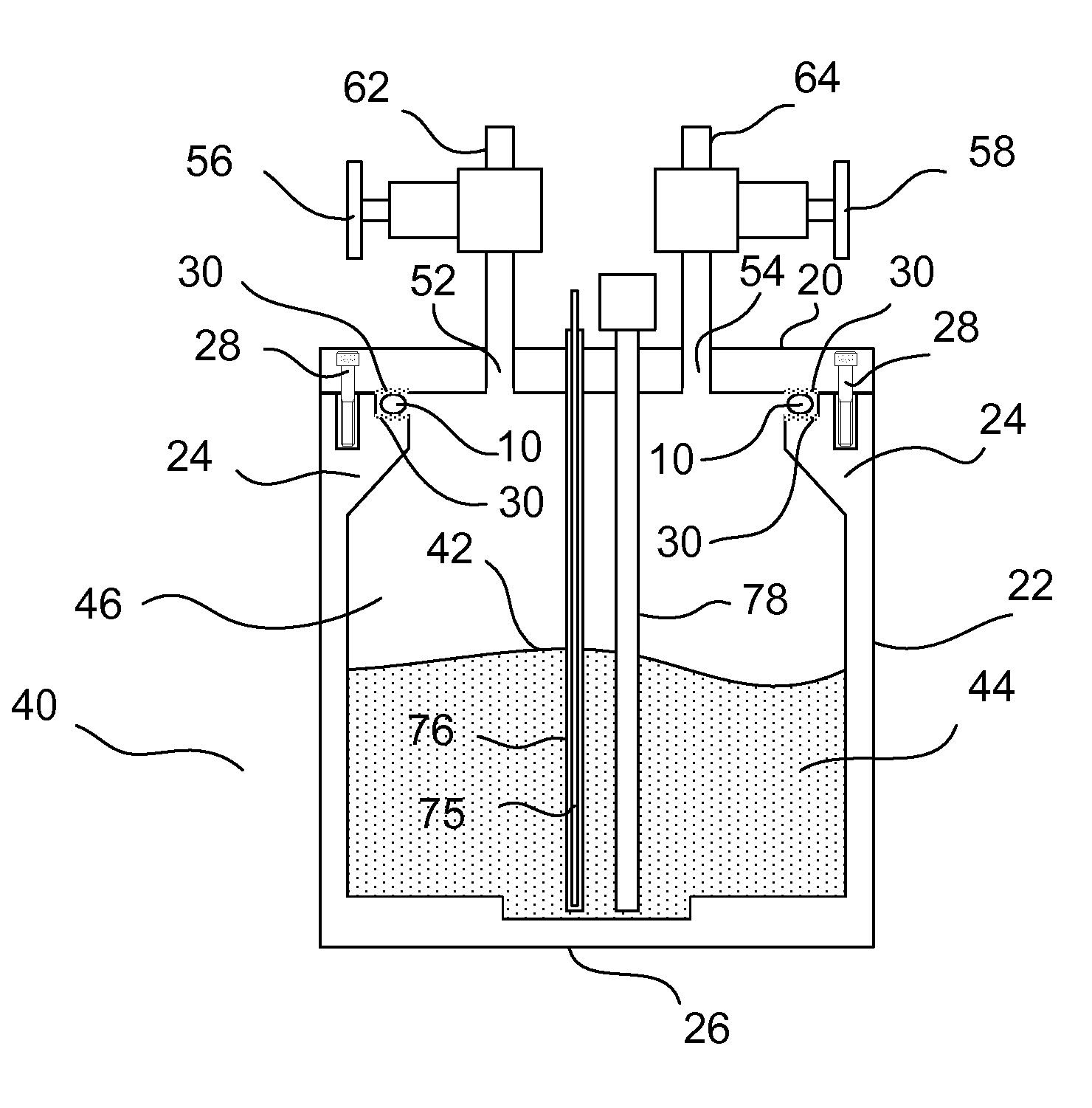
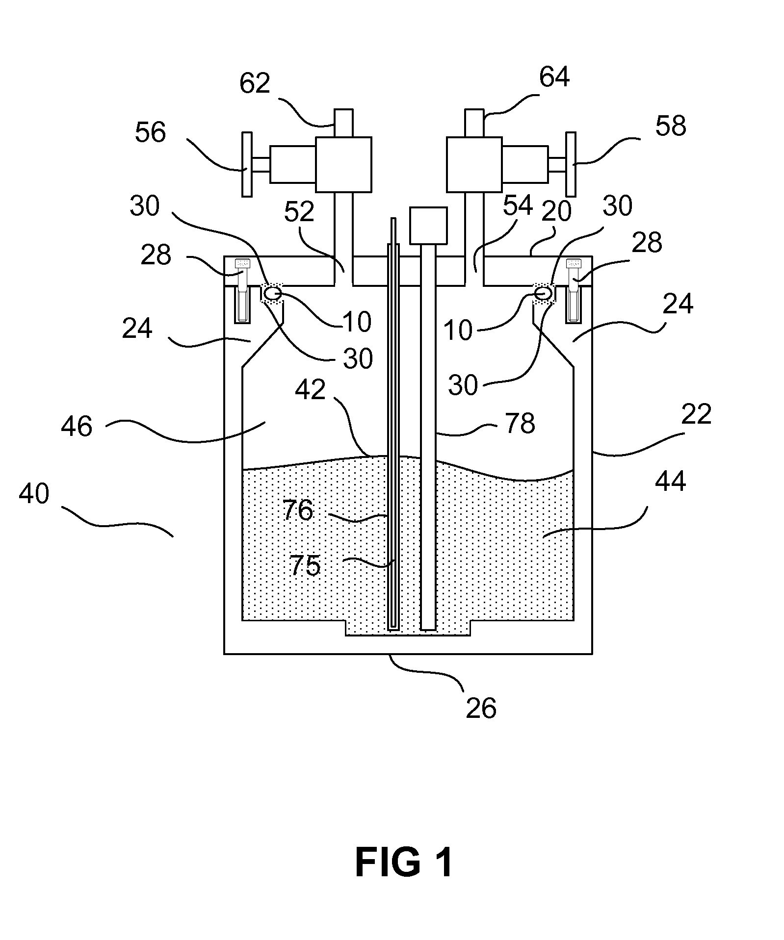
[0304]An ampoule similar to that depicted in FIG. 1 is filled approximately ¾ full with TDMAH. TDMAH is a solid at ambient temperature and melts at approximately 29° C. A source chemical level sensor can be used that is a single point optical type that works by internal reflection of a light source when the sensor is in contact with a liquid. When no liquid is present, there is no internal reflection. The source chemical level sensor sends a signal when the TDMAH precursor content of the ampoule passes the end of the sensor.
[0305]The level sensor can be mounted thru a ¾ inch face seal connection. The temperature sensor can be a K type thermocouple in an all welded thermowell located in the center of the ampoule cover. The thermowell can be filled with a high temperature, heat conducting oil to ensure contact between the temperature sensor and the thermowell. The ends of the thermowell and level sensor extend into ...
PUM
| Property | Measurement | Unit |
|---|---|---|
| diameter | aaaaa | aaaaa |
| height | aaaaa | aaaaa |
| diameter | aaaaa | aaaaa |
Abstract
Description
Claims
Application Information