Rotary valve assembly

a technology of rotary valves and assembly parts, which is applied in the direction of conveyors, vessel construction, marine propulsion, etc., can solve the problems of reducing the sealing area of the valve, a variety of approaches have been tried before with limited success, and the wear life system efficiency is improved. , the effect of increasing the duration of tim

Inactive Publication Date: 2008-07-31
UNITED CONVEYOR CORP
View PDF14 Cites 5 Cited by
  • Summary
  • Abstract
  • Description
  • Claims
  • Application Information

AI Technical Summary

Benefits of technology

[0013]As can be shown from the discussions above, an object of the present invention is to provide an improved wear life system efficiency which is maintained for a greater duration of time.
[0014]A further object of the present invention is to provide a rotary valve with increased durability and decreased maintenance time or down time.
[0015]Still yet another object of the present invention is to provide a rotor with a less complex design having improved abrasion resistance.

Problems solved by technology

A variety of approaches have been tried previously with limited success, and with the creation of separate problems in the upkeep of rotary valve assemblies in the field.
However, such approaches have a variety of limitations.
First, the use of an adjustable shoe or rotor limits the sealing area of the valve to approximately 120 degrees of the rotor circumference.
Second, the body or casing and rotor wear is caused by abrasion.
Abrasive wear, especially in a sealing application such as an airlock, is never smooth.
Instead, the wear is typically in the form of “wire draw,” which looks like grooving on the sealing surface.
The adjustable shoe and rotor designs are dependent upon a smooth or uniform wear on the sealing surfaces, and thus cannot compensate for this type of wear.
If the valve clearance is not checked on a regular basis, it will wear out and eventually fail.
Such maintenance may be time consuming and highly undesirable depending upon the nature of the processing involved.
However, this approach also has a variety of drawbacks.
First, component wear is caused by air leakage through the valve due to differential pressure.
The hard particles in the air stream impact the surfaces of the vanes themselves, causing wear beyond the vane and shroud tips.
Second, the use of cast iron or steel edges that are modified with different alloys to improve hardness are of limited lifespan in abrasive environments because the microstructure and overall hardness of such materials provide limited wear resistance.
Third, while the known use of ceramics and carbides in such applications (typically alumina and tungsten carbide tiles) result in harder and more abrasion resistance than the iron alloys listed above, such an approach still requires the tiles to be mounted to the cast iron body and steel rotor with different types of adhesive.
The unprotected joints between the tiles are prone to abrasive failure.
The adhesives used to mount the tiles also can fail from temperature or by failure of bond to the smooth ceramic surface.

Method used


Image

  • Rotary valve assembly
  • Rotary valve assembly
  • Rotary valve assembly

Examples


Embodiment Construction

[0022]Set forth below is a description of what is currently believed to be the preferred embodiment or best examples of the invention claimed. Future and present alternatives and modifications to this preferred embodiment are contemplated. Any alternatives or modifications which make insubstantial changes in function, in purpose, in structure or in result are intended to be covered by the claims in this patent.

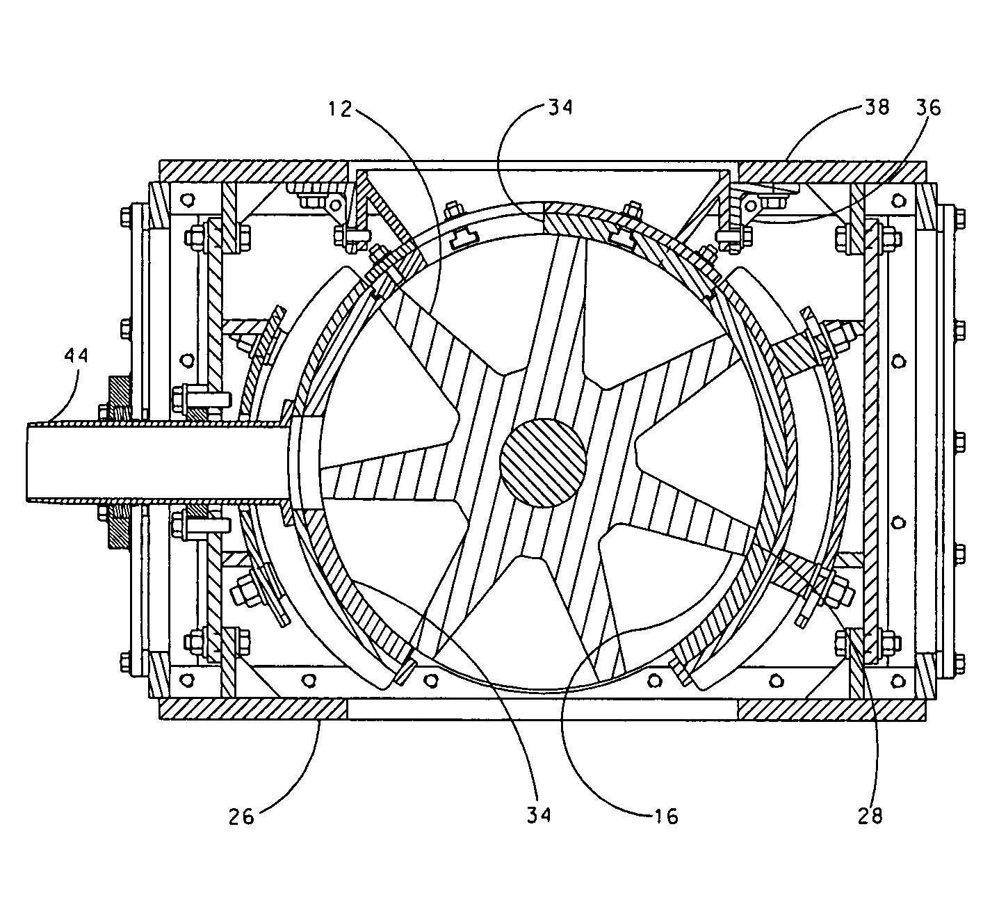
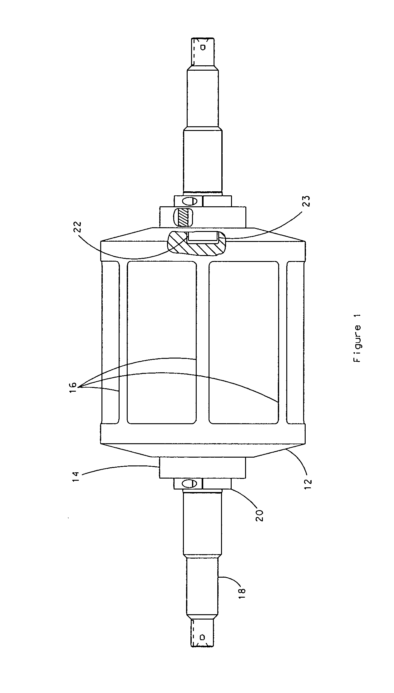
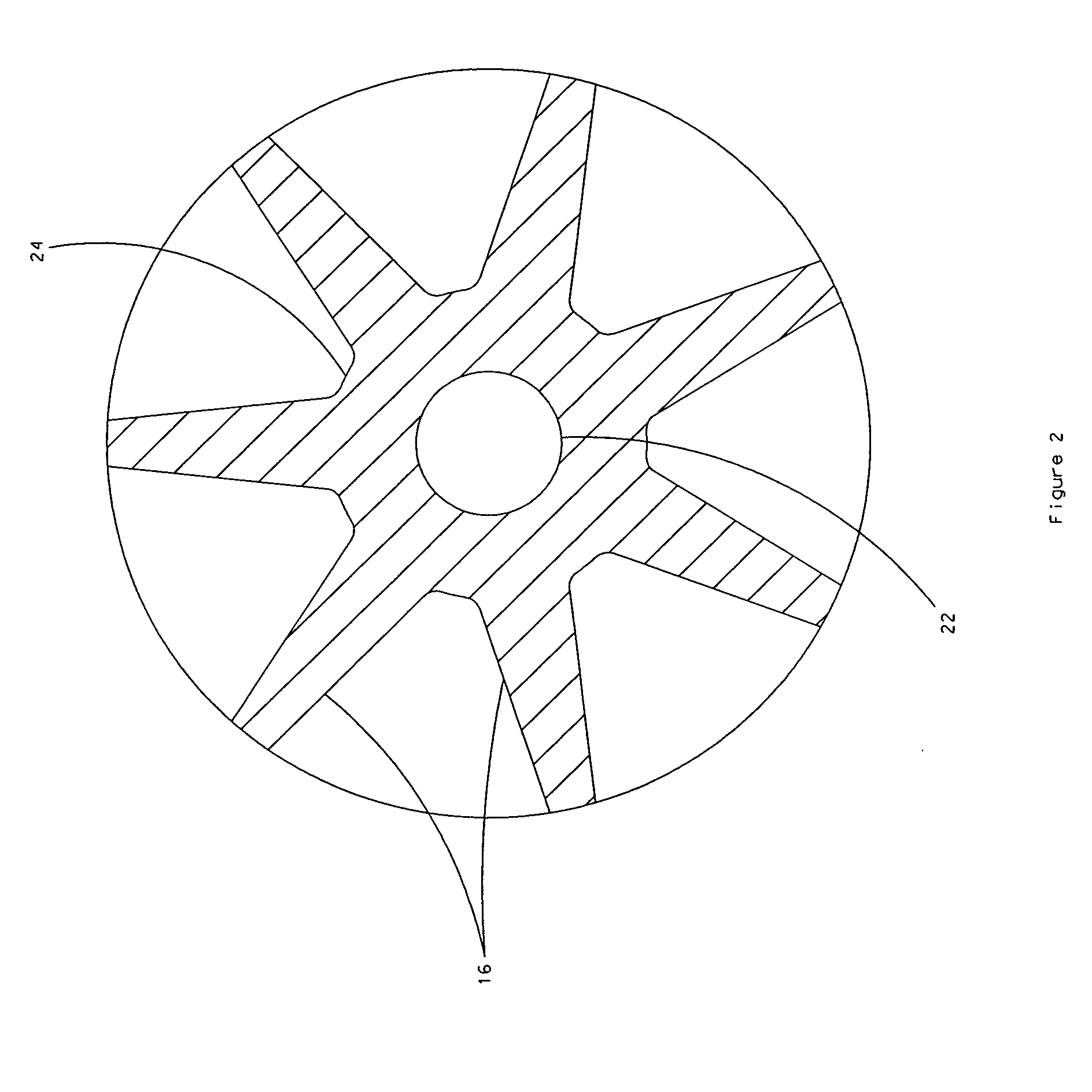
[0023]Referring now to FIG. 1, the rotor assembly 10 of the present invention is preferably comprised of a rotor 12 with vanes 16. The rotor 12 is most preferably constructed out of a unitary piece of silicon carbide. Although other ceramics having a similar hardness are believed to be within the scope of the present invention for example, other carbide compounds having a Mohs hardness value of about 9 or greater. The other major components of the rotor assembly are a shaft 18 and a collar assembly such as a collar clamp 20 and a driver 14. The collar clamp 20 and driver 14 at...


PUM


Abstract

An improved abrasion resistant rotor assembly and valve and system related thereto is disclosed. The assembly includes a rotor body defining an annular opening which surrounds a drive shaft and a plurality of vanes radially extending from the rotor body. The rotor is made up of a unitary ceramic component, such as silicon carbide.
The valve also includes a body for defining a bore that receives the rotor assembly, where the body bore is likewise comprised of a hardened ceramic material. This valve may thus be used to convey abrasive particulate in an efficient manner from a supply container to a pressured line for further processing or disposal.

Description

FIELD OF INVENTION[0001]The present invention relates to rotary valves and an assembly related thereto for handling abrasive materials which is characterized by the use of a plurality of vanes that are made out of a unitary ceramic composition. More specifically, the present invention relates to the use of a unitary ceramic composition for vanes in a rotary valve or similar device comprised of a ceramic composition having a high hardness value, such as silicon carbide. A preferred embodiment of a system including the features of the claimed invention would include a blower or similar device for creating a pressure differential across a rotary valve with vanes comprising a unitary ceramic component.BACKGROUND OF THE INVENTION[0002]Rotary valve assemblies are integral components for handling particulates in a variety of industrial applications, including but not limited to cement, limestone, chemical processing, food processing and coal fired power plant operations. In the past, certa...

Claims


Application Information

Patent Timeline
Patent Type & Authority Applications(United States)
IPC IPC(8): F16K11/074F01D5/22F04C2/00
CPCB65G53/4633Y10T137/86863
Inventor WEENUM, LARRY JONBELOIU, ALEXANDRU S.LEDAIN, ROBERT J.CHARHUT, DANIEL E.
Owner UNITED CONVEYOR CORP
Why Eureka
Try Eureka