Method and apparatus for producing large diameter superalloy ingots

a superalloy and ingot technology, applied in the field of apparatus and methods for melting and atomizing metals and metallics, can solve the problems of ingots that are not suitable for use, ingots that are substantially lacking, and components that are catastrophically damaged

Active Publication Date: 2008-07-31
ATI PROPERTIES
View PDF100 Cites 53 Cited by
  • Summary
  • Abstract
  • Description
  • Claims
  • Application Information

AI Technical Summary

Problems solved by technology

Premium quality nickel-base superalloy ingots are required in certain critical applications including, for example, rotating components in aeronautical or land-based power generation turbines and in other applications in which segregation-related metallurgical defects may result in catastrophic failure of the component.
As used herein, an ingot “substantially lacks” positive and negative segregation when such types of segregation are wholly absent or are present only to an extent that does not make the ingot unsuitable for use in critical applications, such as use for fabrication into rotating components for aeronautical and land-based turbine applications.
Premium quality ingots of these segregation-prone materials, however, are difficult to produce in large diameters by VAR melting, the last step in the triple melt sequence.
In some cases, large diameter ingots are fabricated into single components, so areas of unacceptable segregation in VAR-cast ingots cannot be selectively removed prior to component fabrication.
Consequently, the entire ingot or a portion of the ingot may need to be scrapped.
For example, heat extraction during melting becomes more difficult with increasing ingot diameter, resulting in longer solidification times and deeper molten pools.
Also, larger ingots and electrodes can generate higher thermal stresses during heating and cooling.
However, conventional spray forming generally employs fluid impingement atomization techniques, which present a number of drawbacks.
Impingement using a liquid or certain gases introduces contaminants into the atomized material.
Also, given that fluid impingement does not occur in a vacuum environment, even impingement techniques using inert gases can introduce significant levels of impurities into the atomized material.
Once the region or droplet accumulates sufficient charge exceeding the Rayleigh limit, the region or droplet becomes unstable and is disrupted into fine particles (i.e., atomizes).
In addition, aspects of the initial alloy melting process can present various disadvantages to the overall ingot production process.
Because the superheated metal pool produced by the electron beam is disposed within the high vacuum environment of the furnace melting chamber, the technique also tends to degas the molten material.
This may have a substantial deleterious effect on the chemistry and material properties of a subsequently formed ingot.
Undesirable evaporation must be factored into production and can significantly complicate alloy production when using electron beam melting furnaces.
As noted above, many of the known processes for melting, atomizing and forming alloys to produce solid preforms are deficient in one or more respects.
Such deficiencies include, for example, the existence of oxides and other contaminants in the final product, yield losses due to overspray, and inherent size limitations.
These deficiencies are particularly problematic in the production of certain nickel-base superalloys.

Method used


Image

  • Method and apparatus for producing large diameter superalloy ingots
  • Method and apparatus for producing large diameter superalloy ingots
  • Method and apparatus for producing large diameter superalloy ingots

Examples


embodiment 700

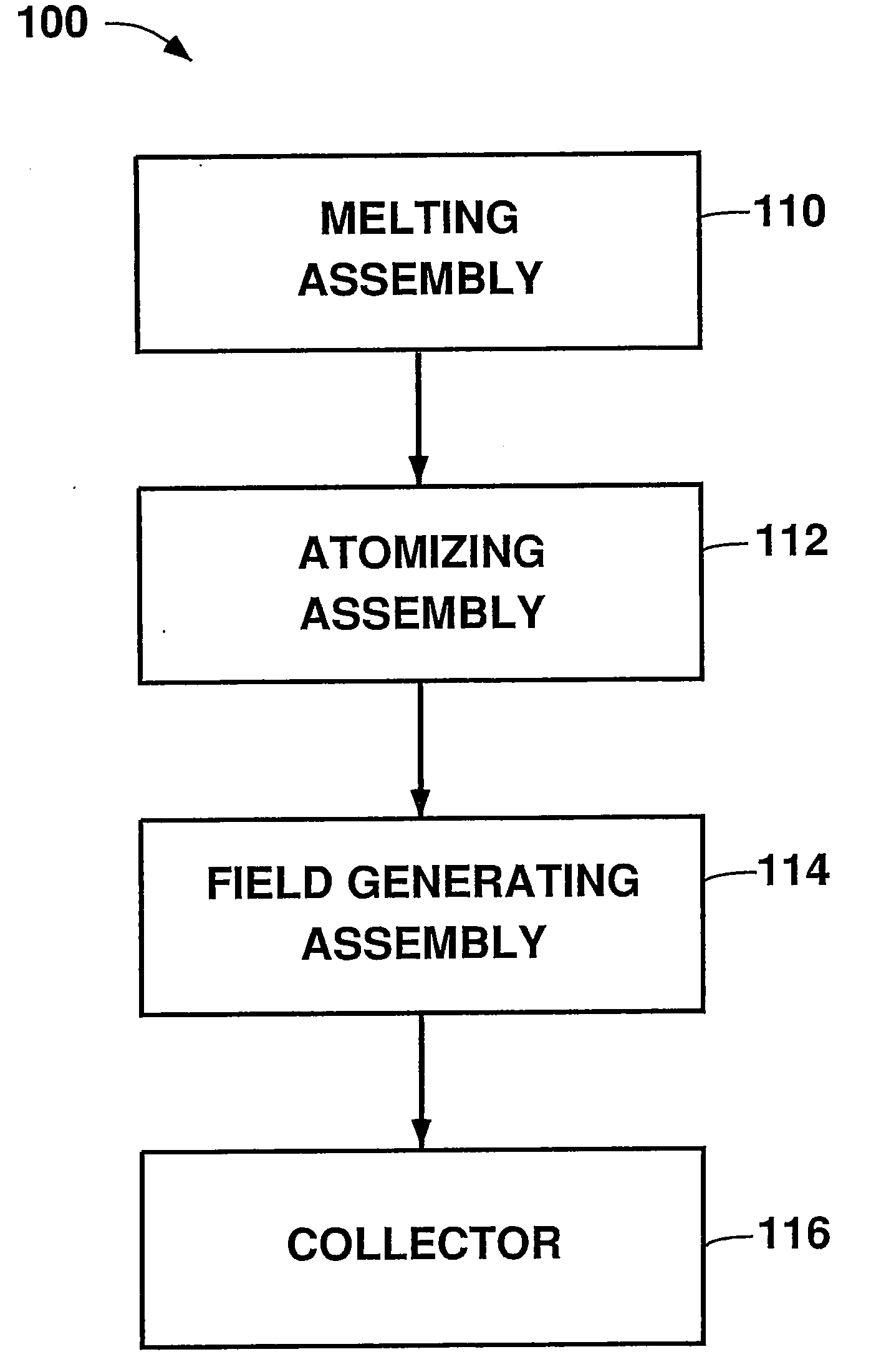
[0123]FIG. 15 schematically illustrates certain elements of an additional non-limiting embodiment 700 of an apparatus constructed according to the present disclosure. Melting assembly 710 supplies at least one of a stream and a series of droplets of molten alloy to electron beam atomizing assembly 712, which produces a spray of charged molten alloy particles 714. Electrostatic field 716 is generated by a field generating assembly between the atomizing assembly 712 and a suitably shaped collector. The field 716 interacts with the charged molten alloy particles 714 to accelerate the particles 714 toward the collector. Particles 714 may be accelerated to a greater extent if the collector is held at a high positive potential. The accelerating force and directional control exerted by field 716 on the charged molten particles 714 may be used to enhance the density of the solid ingot 718, and also may be utilized to produce a near-net shape ingot 718. The collector may be stationary, or ma...

embodiment 800

[0125]FIG. 16 schematically illustrates certain elements of yet another non-limiting embodiment 800 of an apparatus constructed according to the present disclosure, adapted for spray forming a preform. Melting assembly 810, which may be substantially free from ceramic in regions contacting the molten material, provides at least one of a flow and a series of droplets of a molten alloy to an electron beam atomizing assembly 812. The melting assembly 810 optionally may be held at a high negative potential, such as by optional power supply 821, so as to negatively “precharge” the molten material before it passes to the atomizing assembly 812, thereby reducing the quantum of negative charge that the atomizing assembly 812 must convey to the molten material to atomize the material. Such “precharging” feature also may be used with the other embodiments described herein as a means to, for example, reduce the required quantum of negative charge that must be added to the molten material to at...

embodiment 900

[0127]FIG. 17 schematically depicts certain elements of an additional non-limiting embodiment 900 of an apparatus according to the present disclosure, adapted for atomizing molten alloys and forming an ingot. Melting assembly 910 provides at least one of a stream and a series of droplets of a molten alloy to an electron beam atomizing assembly 912. Atomizing assembly 912, which is free from ceramic in regions contacting the molten material, produces charged molten alloy particles 914. Electromagnetic field 916 produced by a magnetic coil 918 (shown sectioned) interacts with the charged molten alloy particles 914 to spread out the particles 914 and reduce the probability of their collision, thereby inhibiting formation of larger molten particles. A second electromagnetic field 940 produced by a magnetic coil 943 (shown sectioned) interacts with and directs the cooled particles 942 toward a collector 944 on which an ingot 946 is developing. This portion of the ingot manufacturing proc...


PUM

PropertyMeasurementUnit
diameteraaaaaaaaaa
diameteraaaaaaaaaa
weightaaaaaaaaaa

Abstract

Methods and apparatus for producing large diameter superalloy ingots are disclosed. A material comprising at least one of a metal and a metallic alloy is introduced into a pressure-regulated chamber in a melting assembly. The material is subjected to a wide-area electron field within the pressure-regulated chamber to heat the material to a temperature above the melting temperature of the material to form a molten alloy. At least one stream of molten alloy from the pressure-regulated chamber is provided from the melting assembly and is fed into an atomizing assembly, where particles of the molten alloy are generated by impinging electrons on the molten alloy to atomize the molten alloy. At least one of an electrostatic field and an electromagnetic field are produced to influence the particles of the molten alloy. The particles of the molten alloy are deposited onto a collector in a spray forming operation to form an alloy ingot.

Description

CROSS-REFERENCE TO RELATED APPLICATIONS[0001]The present application is a continuation-in-part of, and claims priority under 35 U.S.C. §120 to, co-pending U.S. patent application Ser. No. 11 / 232,702, filed Sep. 22, 2005. The present application also claims priority under 35 U.S.C. §119(e) to co-pending U.S. Provisional Patent Application Ser. No. 60 / 909,118, filed Mar. 30, 2007.BACKGROUND OF THE TECHNOLOGY[0002]1. Field of the Invention[0003]The present disclosure relates to apparatus and methods for melting and atomizing metals and metallic (i.e., metal-containing) alloys (collectively referred to herein as “alloys”) to produce atomized molten materials that can be spray formed to produce large diameter alloy ingots. The apparatus and methods employ equipment and techniques that utilize electrons to melt alloys and / or atomize the molten alloys for use in spray forming large diameter alloy ingots having controllable chemistry, microstructure, dimensions, and material properties. The...

Claims


Application Information

Patent Timeline
Patent Type & Authority Applications(United States)
IPC IPC(8): B22D7/00B22D9/00B22D27/02
CPCB22F9/14B22F2009/0836H01J2237/16H01J2237/15H01J2237/063B22F2009/0848B22F2009/0888B22F2009/0896B22F2998/10B32B15/01C22B9/04C22B9/226C22B9/228C22C1/0433C22C19/055C22C19/056C23C4/06C23C4/121C23C4/128H01J37/305H01J2237/06C23C4/123C23C4/137
Inventor FORBES JONES, ROBIN M.
Owner ATI PROPERTIES
Why Eureka
Try Eureka