
Multi-anode system for uniform plating of alloys

a multi-anode system and alloy technology, applied in the field of eiectrodeposition of alloys, can solve the problems of non-uniform alloy composition and non-uniform thickness, non-uniform plating thickness of prior art methods, and basic inability to modify the alloy metal ratio

Active Publication Date: 2008-07-31
MARVELL ASIA PTE LTD
View PDF18 Cites 19 Cited by
  • Summary
  • Abstract
  • Description
  • Claims
  • Application Information

AI Technical Summary

Benefits of technology

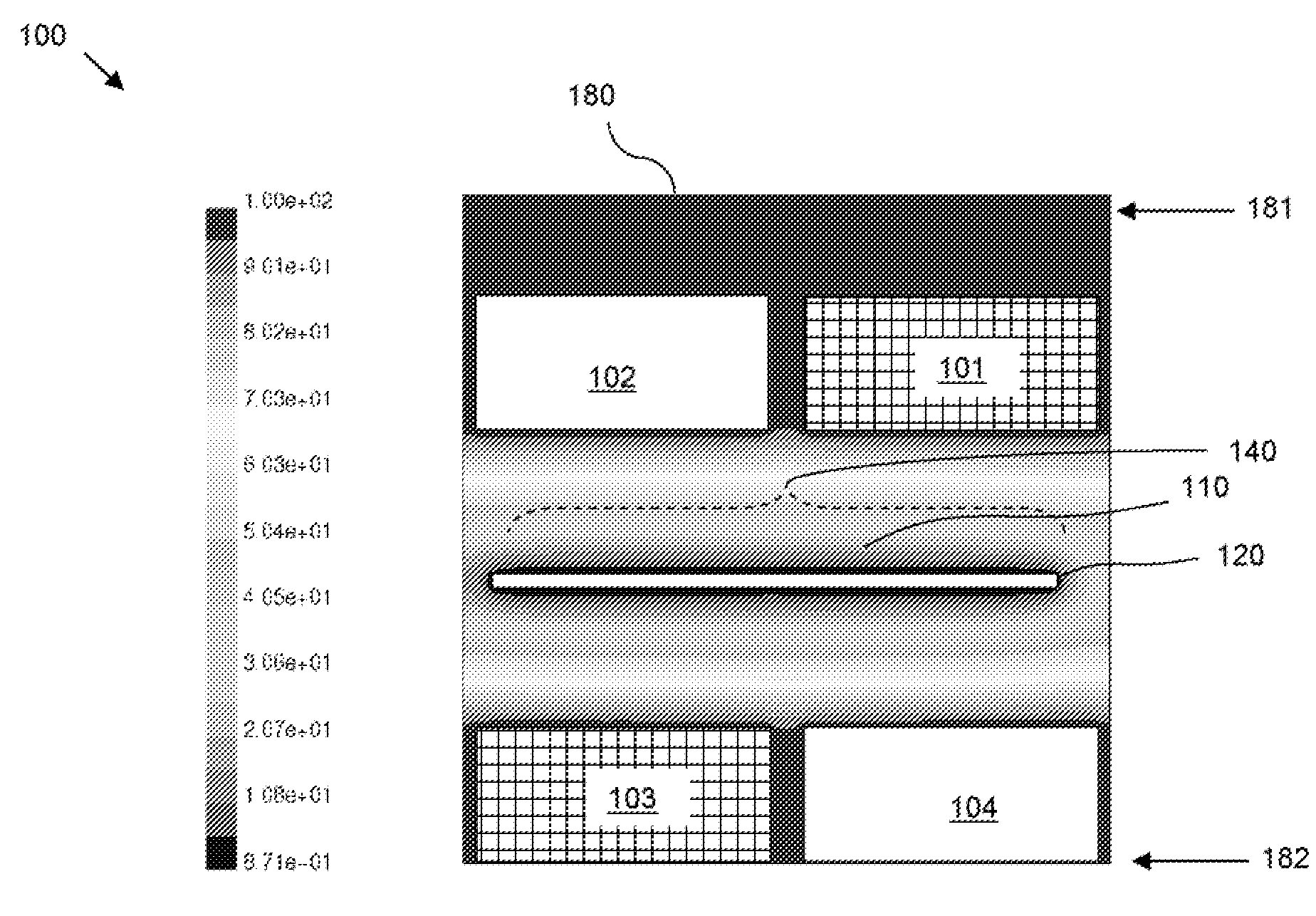
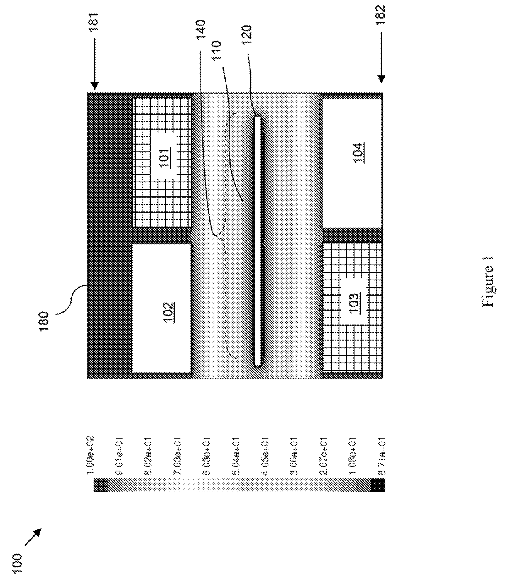
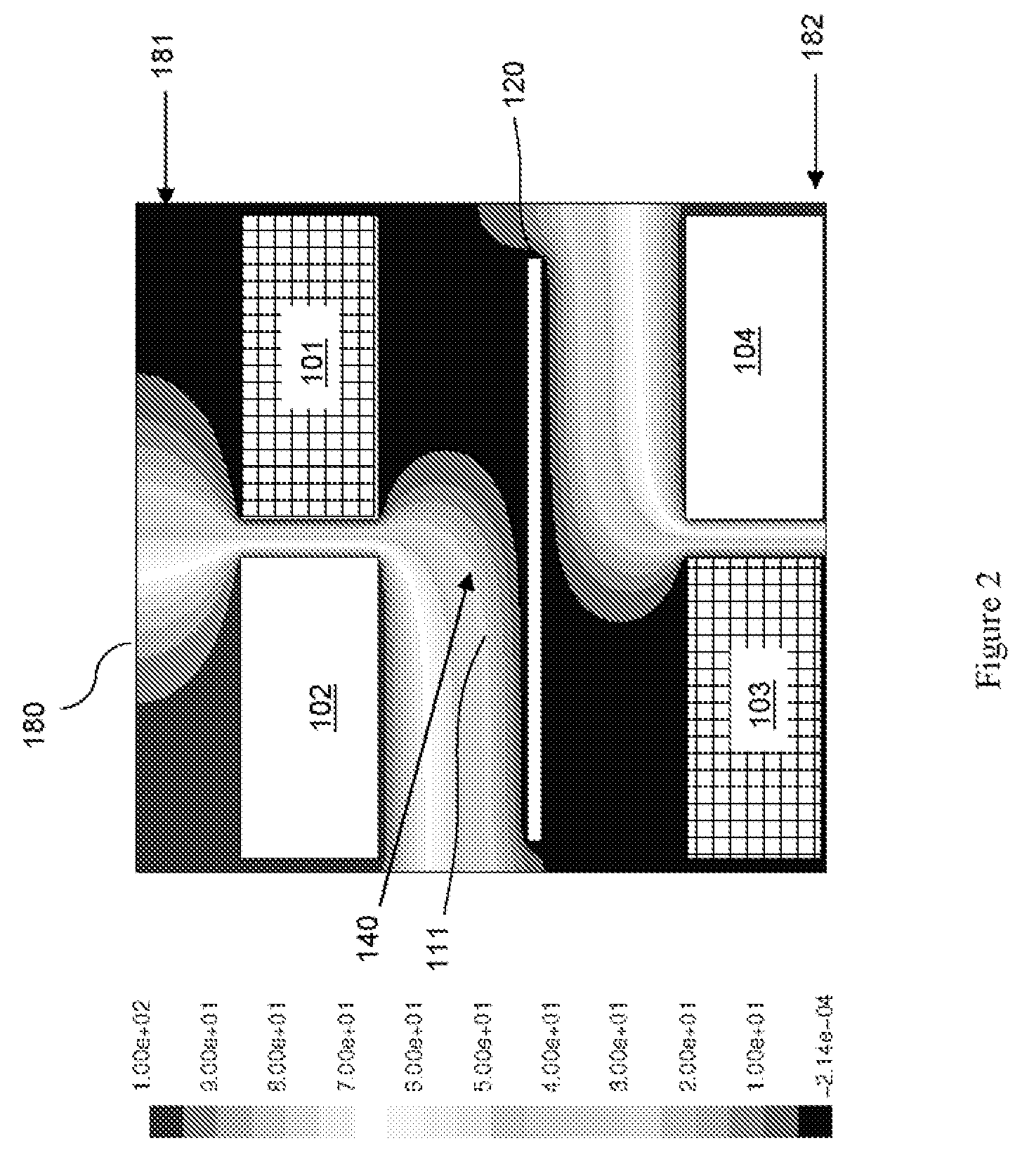
The present invention is an electroplating system and method that allows for the deposition of metal alloys with a uniform plate thickness and the ability to dynamically alter the alloy composition by applying different voltages to the different metals. The system includes multiple anodes with different soluble metals that are placed in an overlapping manner to ensure a uniform current density and potential distribution in the solution near the workpiece. The anodes can have different shapes, placement, and numbers to achieve the desired alloy composition and ensure a uniform plating thickness. The system also includes an electrolyte solution that allows for the simultaneous plating of the workpiece using different anodes with different metals. The anode layers can be predetermined to achieve the desired alloy composition and current density distribution. The system can also include a plating container with a plurality of anode layers that can be selectively varied to achieve the desired alloy composition and thickness.

Problems solved by technology

However, to control the composition and residual stress of the deposited alloy, the plating hath requires frequent chemical additions and eventual dumping.
However, it is basically impossible to modify the alloy metal ratio once the electrodeposition process has started because the ratio of the deposited alloy is for the most part determined by the ratio of the metals in the anode.
However, varying currents in this manner produces a non-uniform voltage profile in the plating bath that typically results in both a non-uniform alloy composition and a non-uniform thickness as compared to the above-described methods.
The system and method further avoids the uneven current density and potential distribution and, thus, the non-uniform plating thickness of prior art methods by selectively varying the shape and placement of the anodes within the plating bath.

Method used


Image

  • Multi-anode system for uniform plating of alloys
  • Multi-anode system for uniform plating of alloys
  • Multi-anode system for uniform plating of alloys

Examples


embodiment 300

[0037]Specifically, FIG. 3a represents a top view of one embodiment 300 of an alloy plating system. FIG. 3b represents a cross-section view of the embodiment 300. In this embodiment, anodes in the same layer comprise the same soluble metal, but the metal type may vary from layer to layer. For example, the anode layers 50 can comprise a first anode layer 301 with at least one first anode 51 comprising a first soluble metal (e.g., nickel) and a second anode layer 302 with at least one second anode 52 comprising a second soluble metal (e.g., cobalt), a third anode layer comprising at least one third anode comprising a third soluble metal, etc. The first anode layer 301 can be positioned adjacent to a first wall 81 of the container 80 and the second anode layer 302 can be positioned adjacent to the first anode layer 301 opposite the first wall 21 of the workpiece 20. Anodes in adjacent anode layers 301, 302 can overlap. For example, the anodes in each layer can be spaced apart at predet...

embodiment 800

[0044]FIG. 8a represents another embodiment 800 of an alloy plating system. In this embodiment 800 each of the anode layers 50 can comprise a plurality of multi-anode structures 855. Each multi-anode structure can comprise at least two different anodes comprising different types of soluble metals. Specifically, each multi-anode structure 855 can comprise a first anode 51 that comprises a first soluble metal (e.g., nickel) and that is surrounded by a second anode 52 that comprises a second soluble metal (e.g., cobalt) that is different from the first soluble metal (e.g., see shapes of exemplary multi-anode structures depicted in FIG. 8a). In this embodiment the first and second anodes 51, 52 can each comprise either non-metal or non-soluble metal (e.g., titanium) baskets or similar type containers with a plurality of openings (e.g., mesh-type openings). The basket of the first anode 51 is filled with pieces (e.g., spheres) of the first soluble metal and is nested within the basket of...


PUM

PropertyMeasurementUnit
surface areasaaaaaaaaaa
areasaaaaaaaaaa
current densityaaaaaaaaaa

Abstract

Disclosed are embodiments of an electroplating system and an associated electroplating method that allow for depositing of metal alloys with a uniform plate thickness and with the means to alter dynamically the alloy composition. Specifically, by using multiple anodes, each with different types of soluble metals, the system and method avoid the need for periodic plating bath replacement and also allow the ratio of metals within the deposited alloy to be selectively varied by applying different voltages to the different metals. The system and method further avoids the uneven current density and potential distribution and, thus, the non-uniform plating thicknesses exhibited by prior art methods by selectively varying the shape and placement of the anodes within the plating bath. Additionally, the system and method allows for fine tuning of the plating thickness by using electrically insulating selectively placed prescribed baffles.

Description

BACKGROUND[0001]1. Field of the Invention[0002]The embodiments of the invention generally relate to eiectrodeposition of alloys and, more particularly, to a multi-anode system and method for eiectrodeposition of alloys.[0003]2. Description of the Related Art[0004]Generally, eiectrodeposition is a process in which, a work-piece to be plated is placed in a plating container with a plating solution (i.e., plating bath). An electrical circuit is created when a negative terminal of a power supply is connected to the workpiece so as to form a cathode and a positive terminal of the power supply is connected to another metal in container so as to form an anode. The plating material is typically a stabilized metal specie (e.g., a metal ion) in the solution. During the plating process this metal specie is replenished with a soluble metal that forms the anode and / or can be added, directly to the solution (e.g., as a metal salt). When an electrical current is passed through the circuit, metal i...

Claims


Application Information

Patent Timeline
Patent Type & Authority Applications(United States)
IPC IPC(8): C25D3/56C25D17/00C25B9/17
CPCC25D17/12C25D17/007C25D17/008
Inventor ARVIN, CHARLES L.BEZAMA, RASCHID J.COX, HARRY D.SEMKOW, KRYSTYNA W.
Owner MARVELL ASIA PTE LTD
Learn More