Single disc dual flow rotary filter

a technology of rotary filter and single disc, which is applied in the direction of moving filter element filter, filtration separation, separation process, etc., can solve the problems of large filter chamber area, limited flow chamber practical limit, and rotating disc filter

Inactive Publication Date: 2008-07-31
PATROVSKY HUBERT
View PDF29 Cites 26 Cited by
  • Summary
  • Abstract
  • Description
  • Claims
  • Application Information

AI Technical Summary

Benefits of technology

[0012]This invention provides a single filtration unit for the special cases of fluids with light to moderate contamination levels and where access to the filter changers is not hazardous. The new filter concept accommodates multiple flow paths and the resulting higher flow rates through a single disc. The filter thus takes up little more space than conventional asymmetric rotary filter units yet offers two filtration flows within little more housing and space constraints than the known single flow asymmetric filter with the added advantage of more balanced forces, uniform temperature conditions, greatly reduced dripage, and a disc axis central to the flow path.
[0013]The invention, by using a disc and a number of highly machined elements in common, and by reducing the size of the elements needed for a given flow, provides for improved costs for this filter concept which is capable of handling two flow streams within a single filter housing and which, by simplification of filter shapes cuts machining.
[0014]The invention further allows close control over temperatures of the filter unit within the metal body blocks that is lacking in large filters and in asymmetric filters which can render very large disc filters inoperable. The use of two or more flow channels also reduces the exposed area of the disc and makes the temperature profile of the disc closer to the ideal condition of no temperature variation in the flow area of the filter. Also it decreases thermal degradation and thermal freezeoff problems.

Problems solved by technology

These design constraints often result in selection of a kidney shaped filter chamber footprint (surface on disc) and a filter chamber shape that looks like a series of bent trapezoids.
A large filter chamber area is a problem due to the amount of fluid required to fill the chamber.
The land widths that provide seals between filter chambers also put a practical limit on the number of flow chambers.
The rotating disc filter also has a disadvantage in that it requires extreme machining accuracy to prevent leaks.
Since surface area and the related problems of machining very flat surfaces increase exponentially with diameter, the size of discs is often governed by the present machining capabilities and disc diameter affects the area of filters that can be accessed in the flow stream and thus limits total flow within a filter.
The requirement for large areas of exposed disc does create problems.
The use of higher temperature polymers and more crystalline polymers in particular creates problems because of the high heat loss due to the exposed disc and the possibility that solid particles of cooled polymer enters the flow stream as new filter chambers enter the filtration area causing process upsets.
In other applications polymers drip, they may be hazardous or have hazardous components, or they may be sensitive to air drying or air reacting with the polymer or fluid.
In these special cases the asymmetric design fails since it has so much exposed disc area.
There are other special cases where filters are used to handle solvent containing polymers where dripage becomes a major problem with the asymmetric filter.
This filter which was designed for maximum access to the filter disc becomes a severe liability since the highly fluid solvent containing stream flows from the filter and through the filter support holes causing solvent and polymer accumulation outside the filter.
As devices are added to existing lines, there is a major space problem There is no compact filter that can handle high volume flows with essentially no pressure variation as the filter media is changed.
In most cases that would indicate that added complexity would seriously lower time between failures.
There is no compact unit in today's marketplace that can provide the function of several filters without lowering the system reliability.

Method used


Image

  • Single disc dual flow rotary filter
  • Single disc dual flow rotary filter
  • Single disc dual flow rotary filter

Examples


seventh embodiment

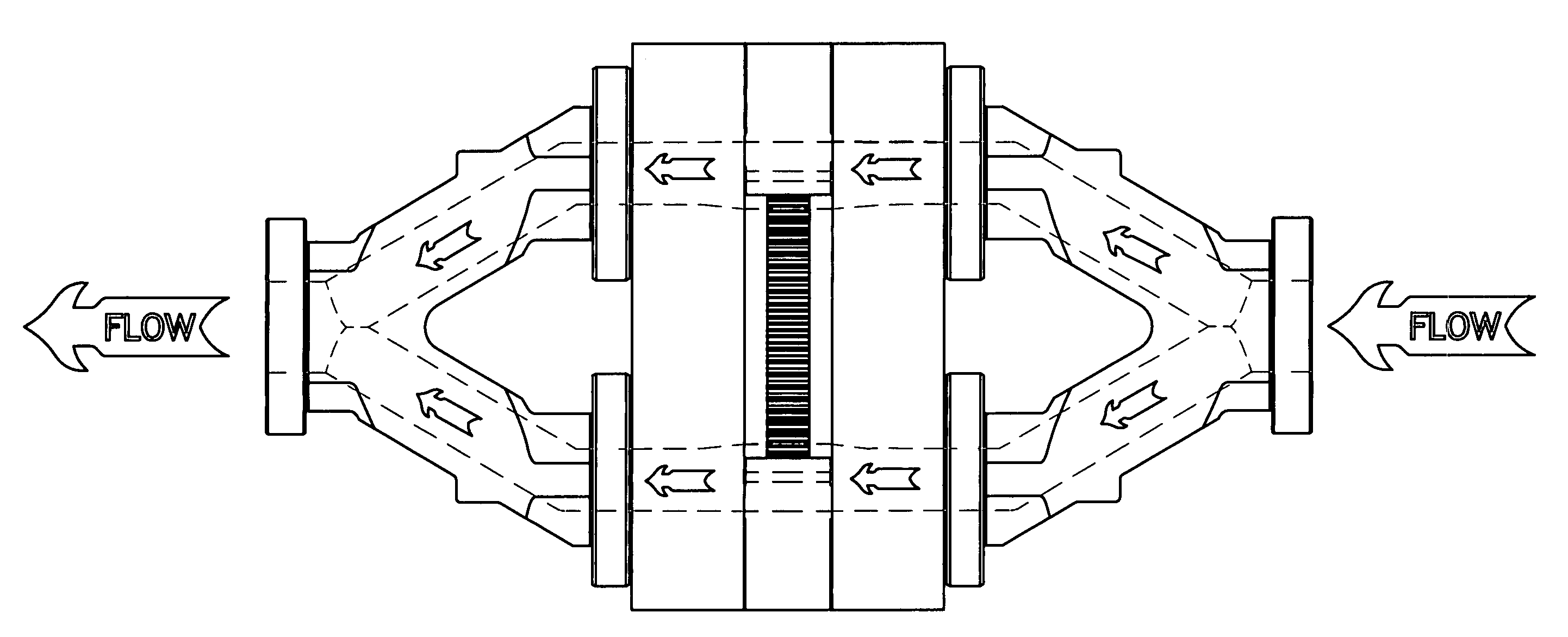
[0050]The filter chambers are shaped in a modified kidney shape which allows pre-filling of the filter chambers with fluid as the filter chambers enter the flow stream and allows improved containment of the fluids trapped in the filter chambers as the filter chambers exit the flow stream due to rotation of the filter chamber containing disc as noted in the Gneuss and the Patrovsky patents cited earlier. The number of filter chambers is ideally an odd number for a rotationally symmetric filter where the flow streams impinge upon the disc 180 degrees from each other around the axis of rotation of the rotary filter disc. If even numbers are used, the modification of the seventh embodiment further improves the flow uniformity.

[0051]The parts are attached to each other by bolts with the first adaptor bolted by bolt hole containing flanges into the input body block, the input body block bolted through center spacer blocks and through hub spacer blocks to the output body block (and also bo...

third embodiment

[0058]In a third embodiment, the adaptor blocks which split the flows into dual streams are incorporated into the input and the output body blocks, eliminating a static seal at the expense of complicating the internal flow passage machining of the respective body blocks.

fourth embodiment

[0059]In a fourth embodiment, the concept of multiple flow streams is expanded to a three flow stream rotary disc filter where three individual flow streams are provided, each identical and rotated by 120 degrees around the axis of rotation from each other. It is noted that the three flow channel filter further limits access to the filter media when the filter media must be changed, and thus this embodiment is best for even lower contamination levels.


PUM

PropertyMeasurementUnit
rotationaaaaaaaaaa
diameteraaaaaaaaaa
sizeaaaaaaaaaa

Abstract

A filter with filter chambers disposed in an annular zone on a rotatable common disc has a multitude of separate flow passages, each flow passage containing within its flow stream at least one filter chamber on the common rotatable disc, and each identical flow passage is rotated around the axis of rotation of this common rotatable disc, thus multiplying the flow capacity of a rotatable disc filter by using the same disc to filter multiple streams. The rotatable common filter disc is disposed within a slot formed by body blocks and spacer blocks and rotates around a hub, the spacer blocks and hub controlling slot width such that rotatable metal to metal seals form between the disc and the body blocks in contact with a surface of the disc, forming leak free seals. The rotation of the rotatable common disc causes filter chambers, sealed within the slot, to change filter chambers as material accumulates within the filter chambers. An extension of the body block in contact with the rotatable disc on the surface without filter chambers provides further support, more temperature uniformity, and prevents fluid dripage. The filter improvement with multiple flow passages provides for higher flow through any specific rotatable filter disc size.

Description

BACKGROUND AND PRIOR ART[0001]The asymmetric rotary filter or rotary disc filter has been on the market for several years. It was first marketed in Europe where a version of a disc filter is covered by European Patent EP o 114 651 B1 (filed in December 1983 by Rehau, AG) and there are two US Patents on the subject, one narrowly drawn to a filter chamber purging method issued as U.S. Pat. No. 4,588,402 to Gneuss and another as U.S. Pat. No. 4,710,288 issued to Hubert Patrovsky (Dec. 1, 1987). A number of asymmetric design rotary disc filters have been sold in the United States and Europe. The disc filter design has unique capabilities to provide a change in filter media with very low variation in the pressure drop across the filter unit. This is due to the shape of the filter chambers and the fact that the lands sealingly separating filter chambers progress through the flow path at a relatively constant amount of exposure so the flow going through the filter remains close to a consta...

Claims


Application Information

Patent Timeline
Patent Type & Authority Applications(United States)
IPC IPC(8): B01D29/09
CPCB29C47/683B29C47/0009B29B7/58B29C48/03B29C48/6914
Inventor PATROVSKY, HUBERT
Owner PATROVSKY HUBERT
Why Eureka
Try Eureka