Dispensing Closure Having Membrane Opening Device With Cutting Teeth

Inactive Publication Date: 2008-07-31
SJI LTD
View PDF9 Cites 33 Cited by
  • Summary
  • Abstract
  • Description
  • Claims
  • Application Information

AI Technical Summary

Benefits of technology

[0120]The use of an open structure also reduces the amount of material required to construct the dispensing closure. This reduces production costs and therefore the cost of the dispensing closure to the consumer.
[0121]The design of the dispensing closure of the current invention allows it to be made in one piece rather than single pieces which are subsequently assembled into a finalised product. This has a number of advantages over earlier dispensing closures which contain a number of components that are made separately and assembled into the final product. These advantages over multi component disclosures include a decrease in manufacturing costs, as there is no assembly required, an increase in the production rate and a decrease in the number of breakages or problems with failed seals between components.
[0122]A feature of the dispensing closure as described herein is the attachment of the membrane opening device to the diaphragm only at certain intervals. This allows greater flexure of the diaphragm thus providing greater movement of the membrane opening device. This also overcomes problems with the prior art caused by the distortion forces between the extended contacts of the membrane opening device and the diaphragm. These forces in prior art dispensing closures reduce their efficiency or may lead to breakdown should the attachment rupture.
[0123]A further advantage of the current

Problems solved by technology

There are however a number of disadvantages with current dispensing closures, such as those listed above.
These relate primarily to difficulties encountered in ensuring that complete mixing of the substances occurs when the dispensing closure is activated.
One disadvantage is that there may be inefficient or only partial breaking of the seal/membrane.
This can restrict the flow of substances between the dispensing closure and the container, leading to incomplete mixing of the substances in the dispensing closure and the container.
Inefficient or incomplete mixing of the two substances is not desired as the concentration of the additive may be critical for some applications, such as in preparing pharmaceutical solutions.
For example, dispensing devices that rupture the membrane by pushing a spike through the membrane to form a hole, such as that disclosed in JP 2004115075, may be ineffective if the hole is not large enough to ensure free flow and mixing of the contents of the dispenser with those of the container to which it is attached in use.
Shaking or other means of forcing the contents of the dispenser to mix with the contents of the container is time consuming and cannot guarantee complete mixing, as, for example, some additive may still remain trapped in the dispenser.
This solution however has the disadvantage of restricting the volume of the available space inside the dispensing closure used to store the additive compound.
This type of dispenser may not be appropriate for use with additives in the form of tablets.
This is a disadvantage of some current dispersers where the hole is small.
This is a disadvantage of dispensers that involve the use of a spike or other solid structure to pierce the membrane as typically the spike remains in close proximity to the hole formed in the pierced membrane after activation.
This type of piercing device typically limits the available space used to store the additive compound inside the dispe

Method used


Image

  • Dispensing Closure Having Membrane Opening Device With Cutting Teeth
  • Dispensing Closure Having Membrane Opening Device With Cutting Teeth
  • Dispensing Closure Having Membrane Opening Device With Cutting Teeth

Examples


Embodiment Construction

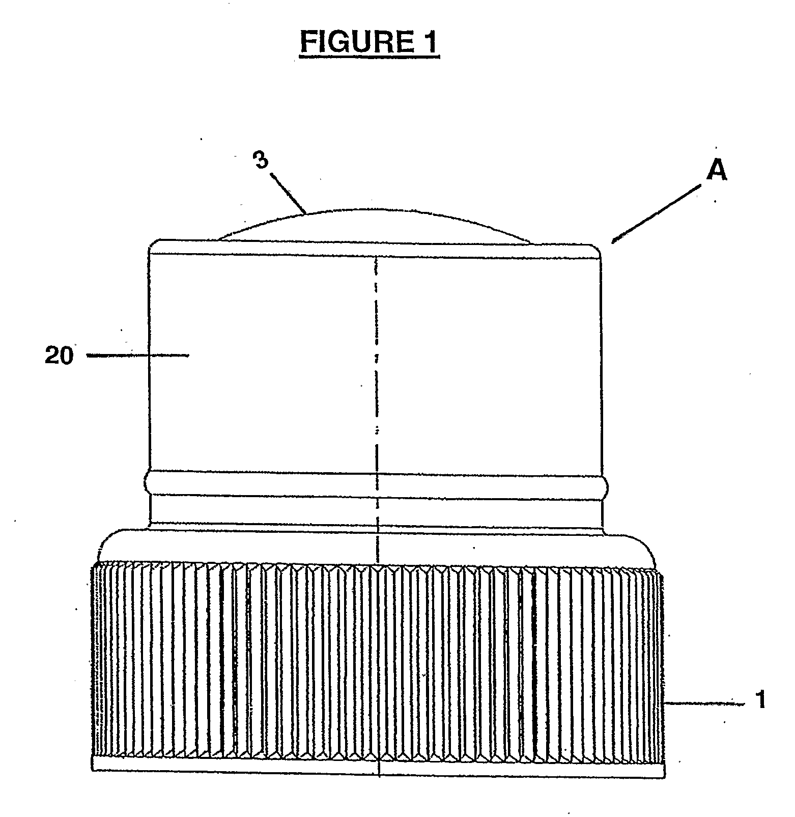
[0134]FIG. 1 shows a side elevation view of the exterior of a dispensing closure device according to the current invention, generally indicated as (A). The dispensing closure device is configured as a lid for a container (not shown in this Figure) where the dispensing closure device is attached to the container via a normal screw threaded closure (1). The dispensing closure device (A) includes a side wall (20) and a flexible diaphragm (3).

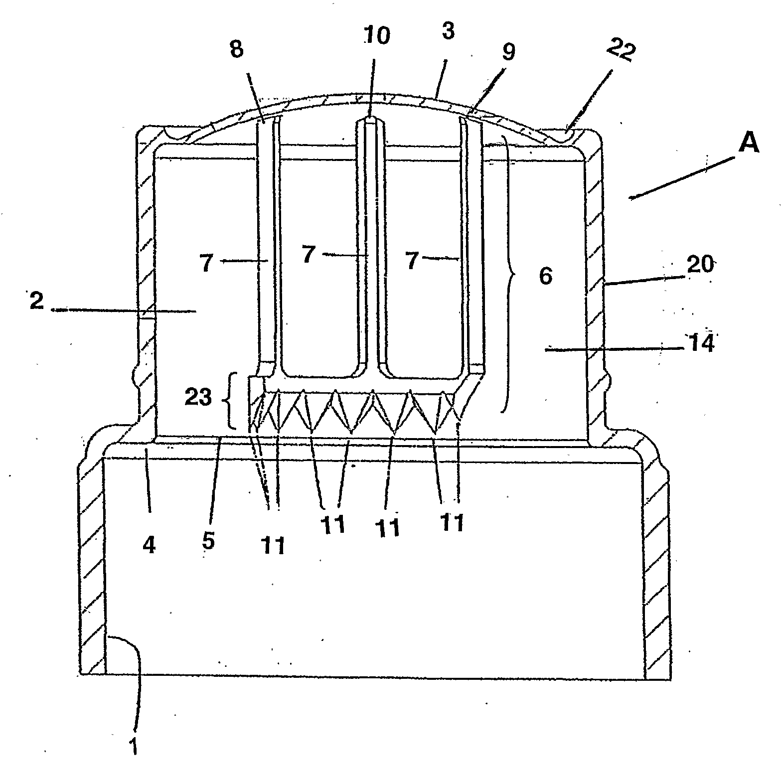
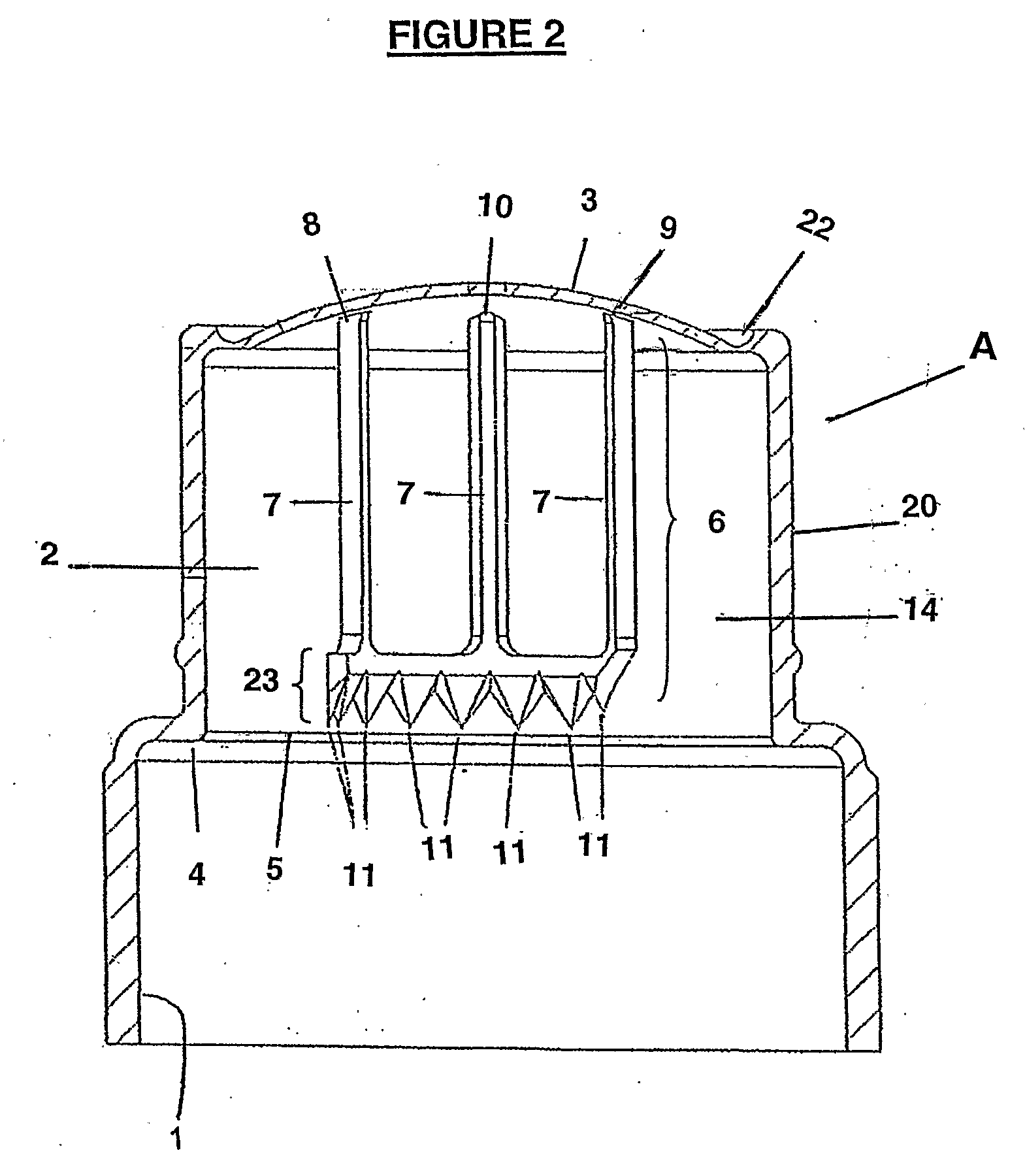
[0135]FIG. 2 shows a vertical cross-sectional view of a dispensing closure (A) including the normal screw threaded closure (1) for attachment to a container (interior screw thread not shown). A storage chamber (2) is formed by the space enclosed by the flexible diaphragm (3), the side wall (20) and the membrane (5) (when fitted).

[0136]A membrane seat (4) is positioned to hold the membrane (5) in position. The top of the container when sealingly attached to the dispensing closure device (A) sits against the side of the membrane seat (4) opposite fro...


PUM


Abstract

A dispenser closure (A) for a container including a storage chamber (2), a flexible diaphragm (3) and a membrane opening device (6) attached to the flexible diaphragm (3), whereby the membrane opening device (6) includes a support structure (7) in the form of an open structure with cutting teeth (11) in which a substance, additive, ingredient or powder to be dispensed may flow and out through the opened membrane. The open support structure results in mixing to occur immediately when the membrane is open, enables free movement of the substance, and facilitates complete mixing as there are fewer surfaces to trap the substance. Upon depression of the flexible diaphragm, the cutting teeth (11) of the opening device (6) moves to cut the membrane (5) thereby opening the storage chamber to allow the substance to mix with water, a solution or a sports drink contained in an attached container or bottle.

Description

TECHNICAL FIELD[0001]This invention relates to a dispensing closure to be used in conjunction with a container.[0002]In particular the present invention relates to a dispensing closure that keeps two or more substances separate until the dispensing closure is activated, thus enabling the substances to be mixed.BACKGROUND ART[0003]Dispensers are used frequently to hold and, when activated, to add additives to water, other solutions or powders. These are often in the form of a dispensing closure which can be attached to a bottle or container in which the water, other solution or powder to which the additive is to be added, is contained. The dispensing closure holds the additive and once activated enables the substances to mix.[0004]For example, dispensing closures are widely used in the pharmaceutical industry to keep one or more active ingredients separate from the solution in which they may be used, until the mixture is required. This is particularly useful in situations where the e...

Claims


Application Information

Patent Timeline
IPC IPC(8): B65D25/04B67D5/00B67D99/00
CPCB65D51/224B65D2251/0031B65D2251/0028B65D51/2835
Inventor SHARP, JEFFREY JOHN
Owner SJI LTD
Why Eureka
Try Eureka