Upgradeable Automation Devices, Systems, Architectures, and Methods

a technology of automation devices and automation devices, applied in the field of automatic systems, can solve the problems of not substantially broadening the market for these products, and difficult implementation and maintenance of home automation systems, etc., to achieve the effect of reducing energy consumption and reducing energy cost and/or consumption

Inactive Publication Date: 2008-07-31
AUTAMI CORP
View PDF57 Cites 188 Cited by
  • Summary
  • Abstract
  • Description
  • Claims
  • Application Information

AI Technical Summary

Benefits of technology

[0038]At another level, the automation controller can coordinate the different energy management activities within a facility and/or work space. For example, a work space environment will be defined at least in part by the temperature and lighting intensity. The automation controller can be configured to balance the solar impact, i.e., light and heat provided by sunlight, within an area with the light and heating/cooling provided by the building systems to minimize the energy cost and/or consumption. In this c

Problems solved by technology

A major reason being that home automation systems tend to be difficult to implement and maintain and/or extremely expensive relative to the utility and benefits of the system.
Common criticisms of X10 are directed toward its reliability and robustness, as well as the level of user-friendliness.
Other PLC protocols have been developed to address the criticisms of X10, which have enhanced performance and user experience, but have not substantially broadened the market for these products.
The high-end of the residential market has typically been addressed by comprehensive and expensive stand-alone systems, which often require the use of professional services firms to install and possibly maintain the system.
In addition to the price of the comprehensive system, the co

Method used


Image

  • Upgradeable Automation Devices, Systems, Architectures, and Methods
  • Upgradeable Automation Devices, Systems, Architectures, and Methods
  • Upgradeable Automation Devices, Systems, Architectures, and Methods

Examples


Embodiment Construction

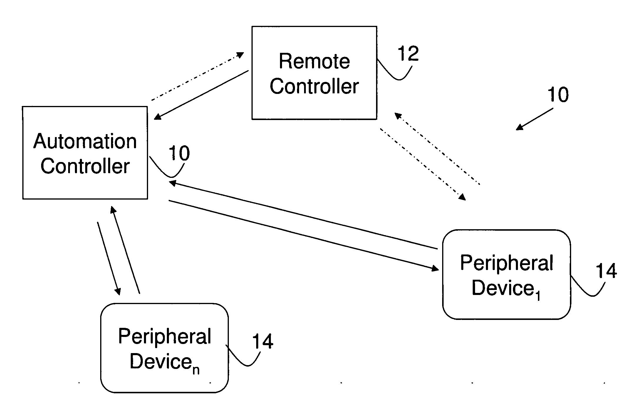
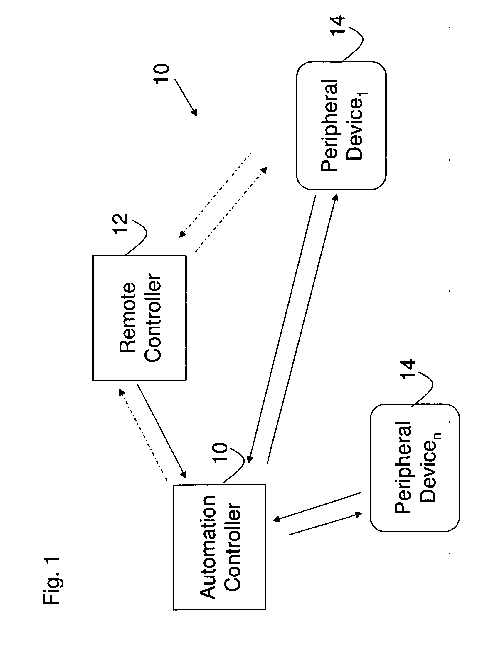
[0047]FIG. 1 depicts an automation system 10 embodiment of the present invention. The system 10 includes various components, such as an automation controller 12, a remote controller 14, and one or more peripheral devices 161-n. In this embodiment, the automation controller 12 has two way communications with the peripheral device 16 (as shown by the solid arrows). It also has at least one way communication with the remote controller 14, and, optionally two way communications with the remote controller 14 (as indicated by the dashed arrows). In addition, the remote controller 14 can have optional one or two way communications with one or more of the peripheral devices 161-n

[0048]Communication between the automation controller 12 and the peripheral devices 16 can be wired and / or wireless depending upon the particular implementation. Wired communication can make use of the power lines, local area networks, or direct links between communication ports, such as USB, RS-232 and 485, etc. W...


PUM


Abstract

A multi-level automation control architecture, methods, and systems are disclosed, which provide enhanced scalability, functionality, and cost effectiveness for energy, access, and control. The systems include various combinations of automation controllers, remote controllers and peripheral devices that are used to provide monitoring and control functionality over the various systems in a structure, such as HVAC, water, lighting, etc. In various embodiments, the automation controller and various peripheral devices are implemented to provide an integrated energy management system for the structure. The system allows the user to manage energy based on the day, time, the presence of people, and the availability of natural lighting and heating, as well as prioritize and participate in demand-response program. The system can be implemented using a remote controller and expanded through the addition of automation controllers, remote controllers, and peripheral devices to enable the system to be tailored to specific user requirements.

Description

CROSS-REFERENCE TO RELATED APPLICATIONS[0001]This application claims the benefit of U.S. Provisional Patent Application No. 60 / 886,918 filed Jan. 26, 2007 and is related to U.S. Patent Application entitled “Upgradeable Automation Devices, Systems, Architectures, and Methods for Energy Management” filed on even date herewith having attorney docket number 20070126B.STATEMENT REGARDING FEDERALLY-SPONSORED RESEARCH AND DEVELOPMENT[0002]Not Applicable.FIELD OF THE INVENTION[0003]The present invention is directed generally to automation systems and, more specifically, to automation systems to monitor and control conditions in and / or around buildings and the operation of energy systems.BACKGROUND OF THE INVENTION[0004]Automation of the work and leisure environment has been a concept that has been long pursued. Despite the continued pursuit, widespread automation, particularly in the home, has not gone much beyond the use of timers, programmable thermostats, and universal remote controls fo...

Claims


Application Information

Patent Timeline
IPC IPC(8): G05B11/01
CPCG05B19/042H05B37/0245G05B11/01G05B2219/2642H05B47/175
Inventor CLAYTON, RANDYANTONE, MICHAELRAHME, DANIEL
Owner AUTAMI CORP
Why Eureka
Try Eureka