Basement wall and floor system

a technology of floor system and foundation wall, which is applied in the direction of walls, cellars, building repairs, etc., can solve the problems of low thermal insulation properties, damp and clammy basements with concrete walls, and high construction costs

Inactive Publication Date: 2008-08-07
SKADERI GRUP LLC
View PDF16 Cites 19 Cited by
  • Summary
  • Abstract
  • Description
  • Claims
  • Application Information

AI Technical Summary

Benefits of technology

[0006]The present invention provides a basement wall system that overcomes the disadvantages of conventional concrete basement walls. The basement wall system also provides a high level of thermal insulation, waterproofing, and protection against insect damage. The basement wall system includes a plurality of connected panel sections, and the panel sections may also be used to form a basement floor system.

Problems solved by technology

This delay in construction is undesirable because it can result in higher construction costs.
Another disadvantage with concrete basement walls is that they have a relatively high capacity for absorbing and conveying moisture through capillary action, and as a result, basements with concrete walls tend to be damp and clammy.
A further disadvantage with concrete basement walls is that they have relatively low thermal insulating properties.
As a result, basements with concrete walls tend to be relatively cool and generally uncomfortable during the winter months.
During the backfill process, the basement wall may be damaged by material or machinery that comes into contact with the wall.

Method used


Image

  • Basement wall and floor system
  • Basement wall and floor system
  • Basement wall and floor system

Examples


Embodiment Construction

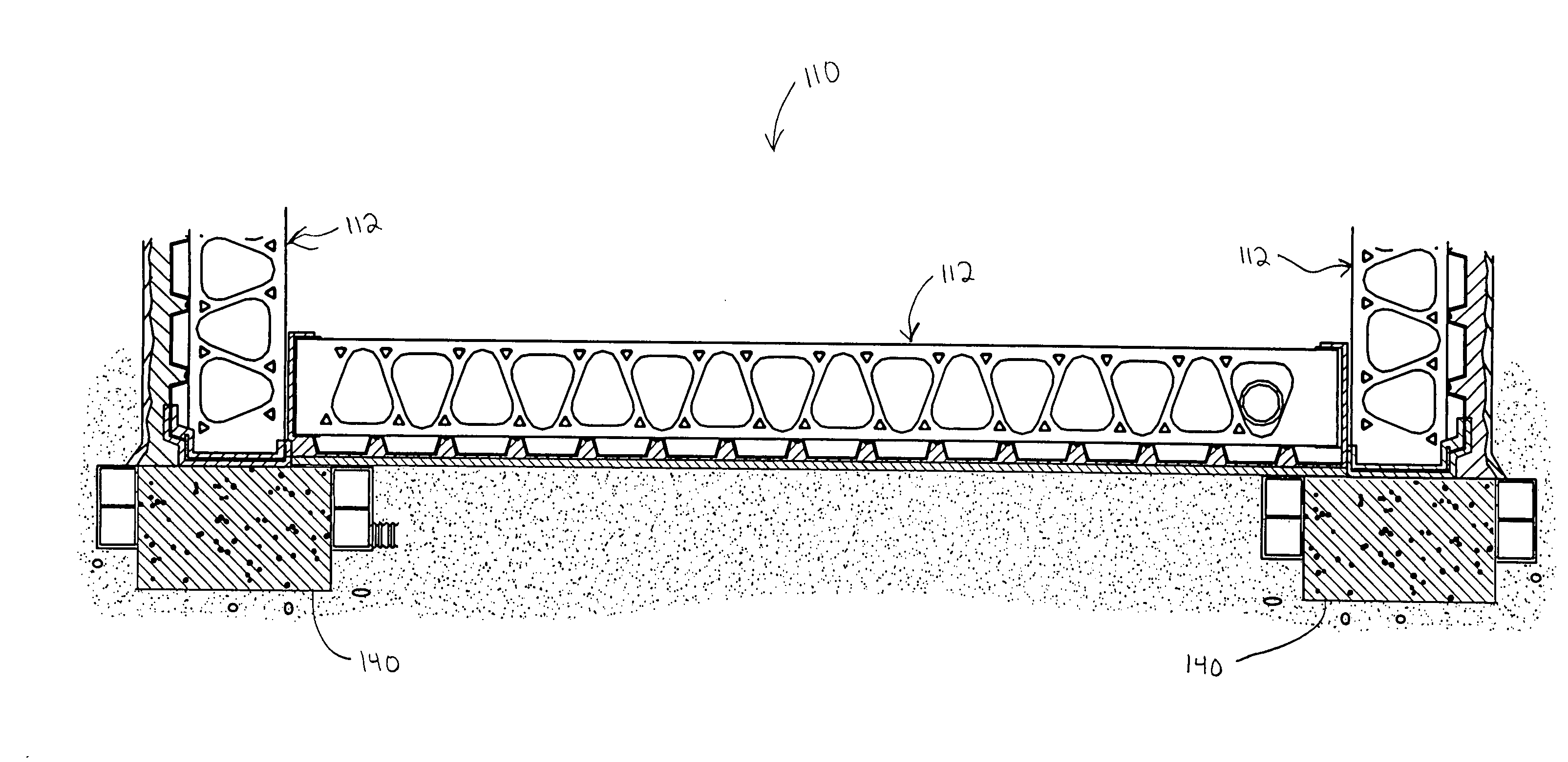
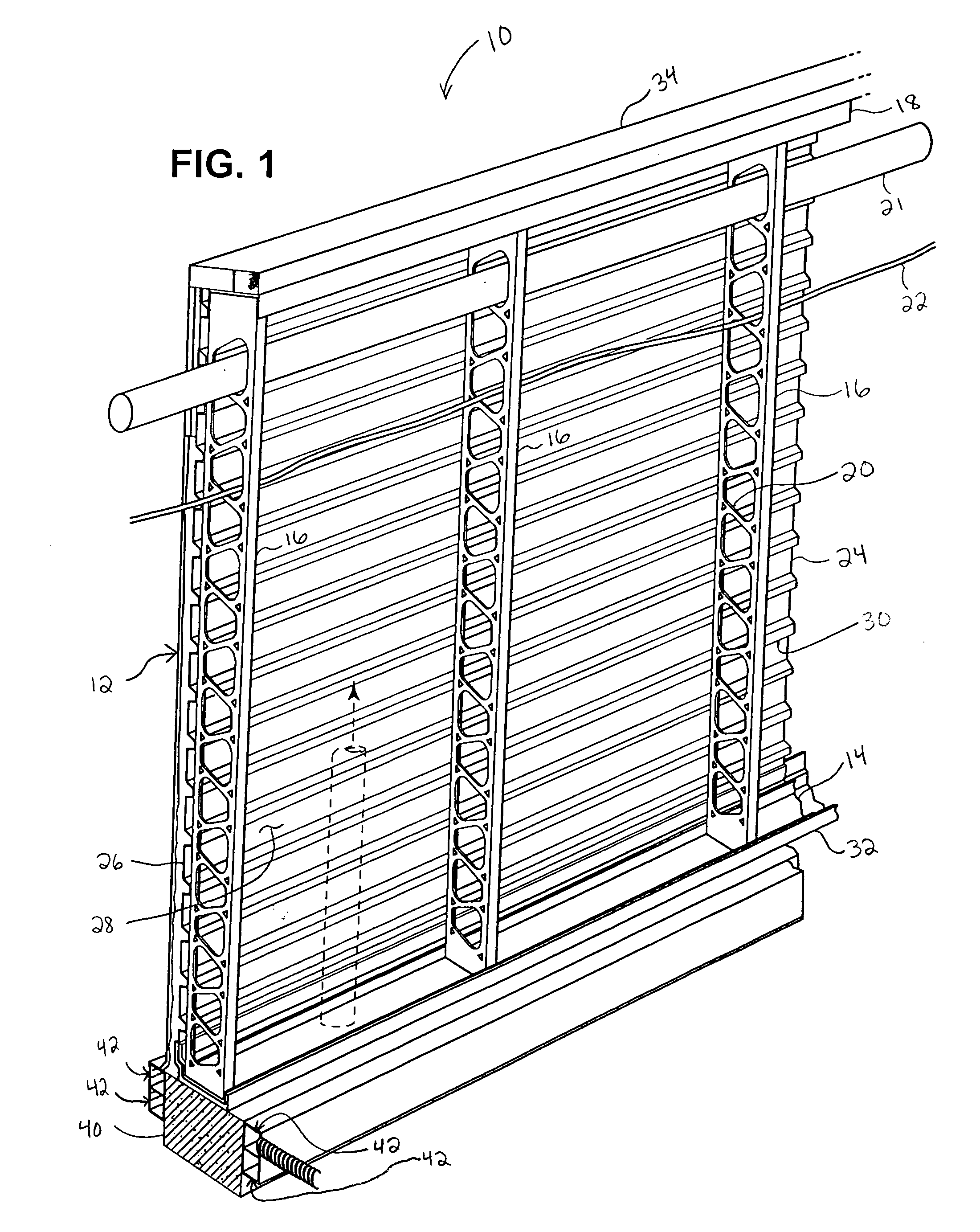
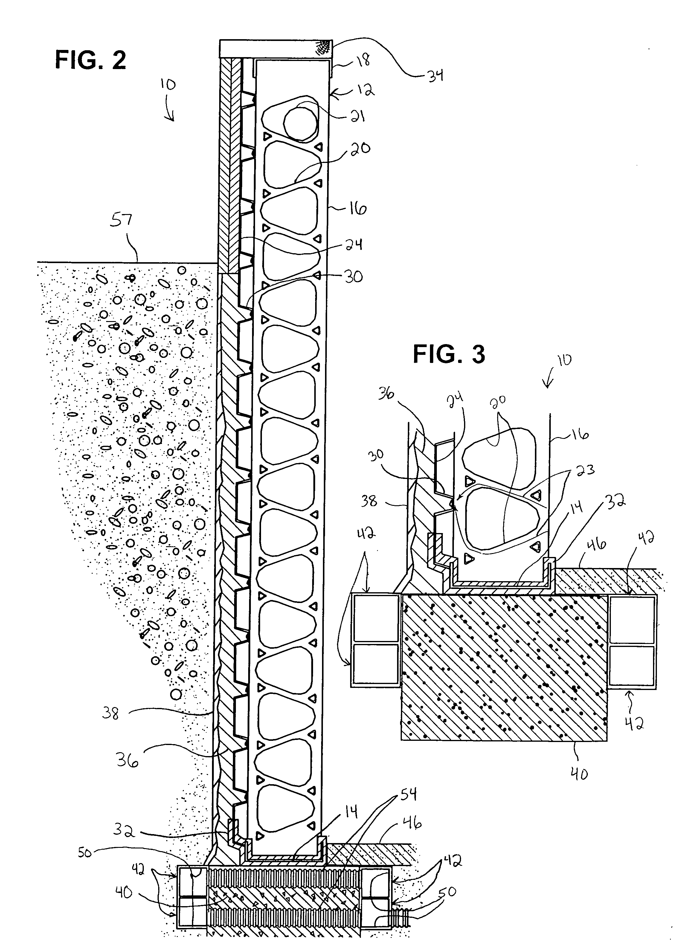
[0022]Referring now to the drawings in detail, numeral 10 generally indicates a basement wall system in accordance with the invention. Turning first to FIGS. 1 through 3, the basement wall system 10 includes a plurality of connected panels 12. Each panel 12 includes a lower metal C-channel 14 having a horizontally disposed base portion, an outside vertically disposed flange portion, and an inside vertically disposed flange portion. The C-channel 14 defines an end of the panel 12. A plurality of vertically disposed metal studs 16 extend upwardly from the base portion of the C-channel. The lower end of each stud 16 generally fits snugly between the inside and outside flange portions of the lower C-channel 14. The studs 16 may be fixed to the C-channel 14, such as by welding. All welds may be coated, such as by spraying, with a rust inhibitor. The basement wall system 10 also includes an upper C-channel 18 having a horizontally disposed middle portion, an outside vertically disposed fl...


PUM


Abstract

A basement wall and floor system includes a plurality of connected horizontally and vertically disposed panels. Each panel includes a metal C-channel defining an end thereof. Another metal C-channel defines an opposite end. A plurality of metal studs extend between the C-channels and fit between inside and outside flanges of the C-channels. A metal deck including an outwardly disposed facade and an inwardly disposed face is connected to the studs. Insulation is disposed on the facade side of the metal deck. A waterproofing material is disposed on the insulation.

Description

CROSS REFERENCE TO RELATED APPLICATION[0001]This application claims the benefit of U.S. Provisional Application No. 60 / 899,298, filed Feb. 2, 2007.TECHNICAL FIELD[0002]This invention relates to a basement wall system and a basement wall and floor system for a building, and more particularly to a basement wall and floor system that is highly moisture resistant, thermally efficient, durable, and capable of being quickly constructed in comparison to conventional concrete walls and floors.BACKGROUND OF THE INVENTION[0003]Basement walls for residential buildings have generally been constructed of concrete. Typically, spaced apart vertical forms are assembled at a building site, and concrete is poured into the space defined between the forms. After the concrete has been poured, it must be allowed to set or cure for a period of several days, and often as much as two weeks or even longer. Construction of a building having a poured concrete wall must be completely suspended during the time t...

Claims


Application Information

Patent Timeline
Patent Type & Authority Applications(United States)
IPC IPC(8): E04B1/74
CPCE02D31/00E04B1/0007E02D31/02E02D31/008
Inventor FORNER, CHARLES K.SCUDERI, SALVATORE C.
Owner SKADERI GRUP LLC
Why Eureka
Try Eureka