
Method and apparatus for in-situ sample preparation

a technology of in-situ sample preparation and apparatus, which is applied in the direction of instruments, separation processes, therapy, etc., can solve the problems of difficult, expensive and time-consuming to carry out tem inspection, and the inspection of cross-sectional thin slices of specimens, particularly the inspection of membranes of wafers or chips, is expensive, and the failure analysis of integrated circuits is difficult to carry out cross-sectional inspections on a regular basis

Active Publication Date: 2008-08-07
ICT INTEGRATED CIRCUIT TESTING GESELLSCHAFT FUER HALBLEITERPRUEFTECHNIK GMBH
View PDF13 Cites 17 Cited by
  • Summary
  • Abstract
  • Description
  • Claims
  • Application Information

AI Technical Summary

Benefits of technology

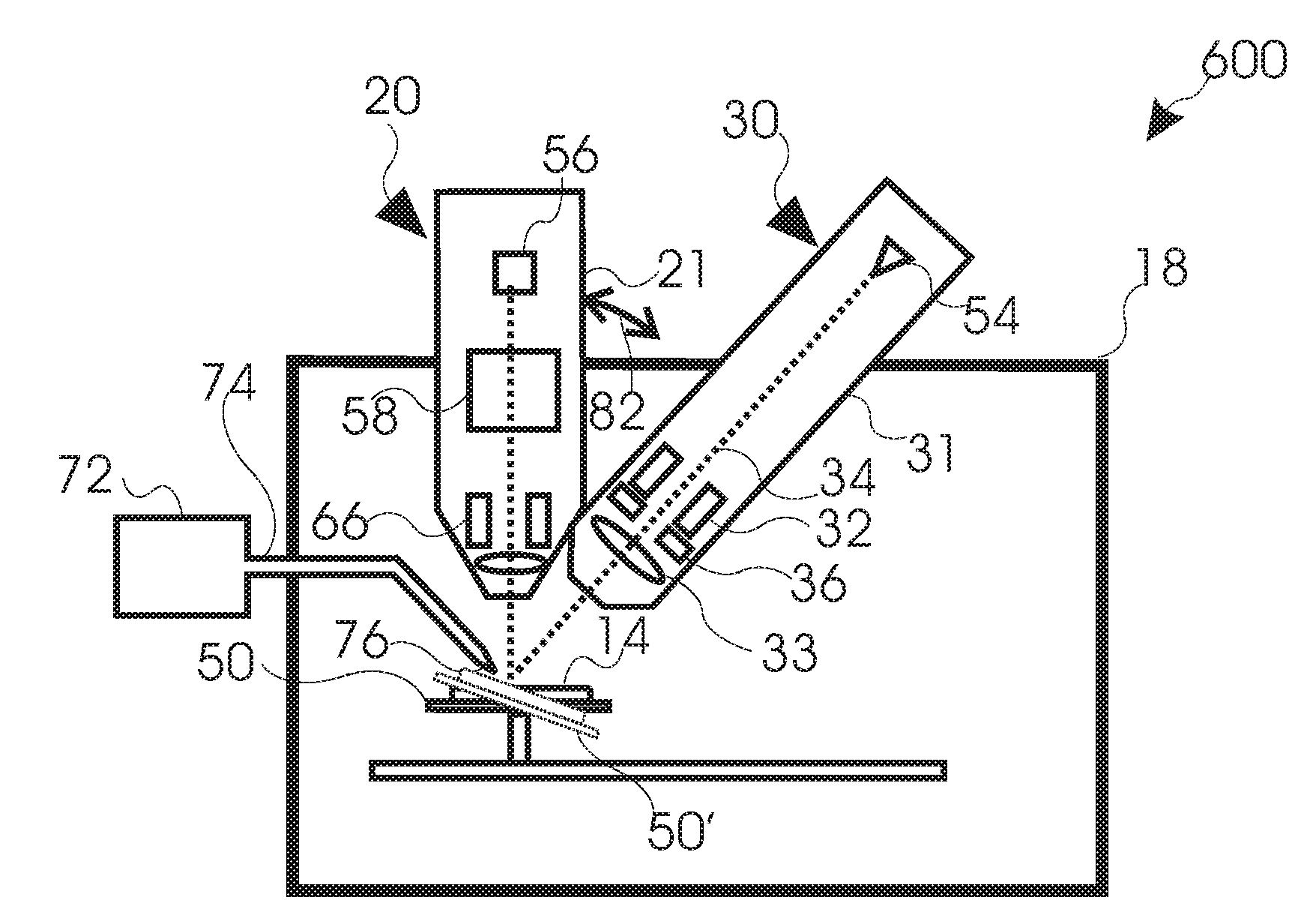
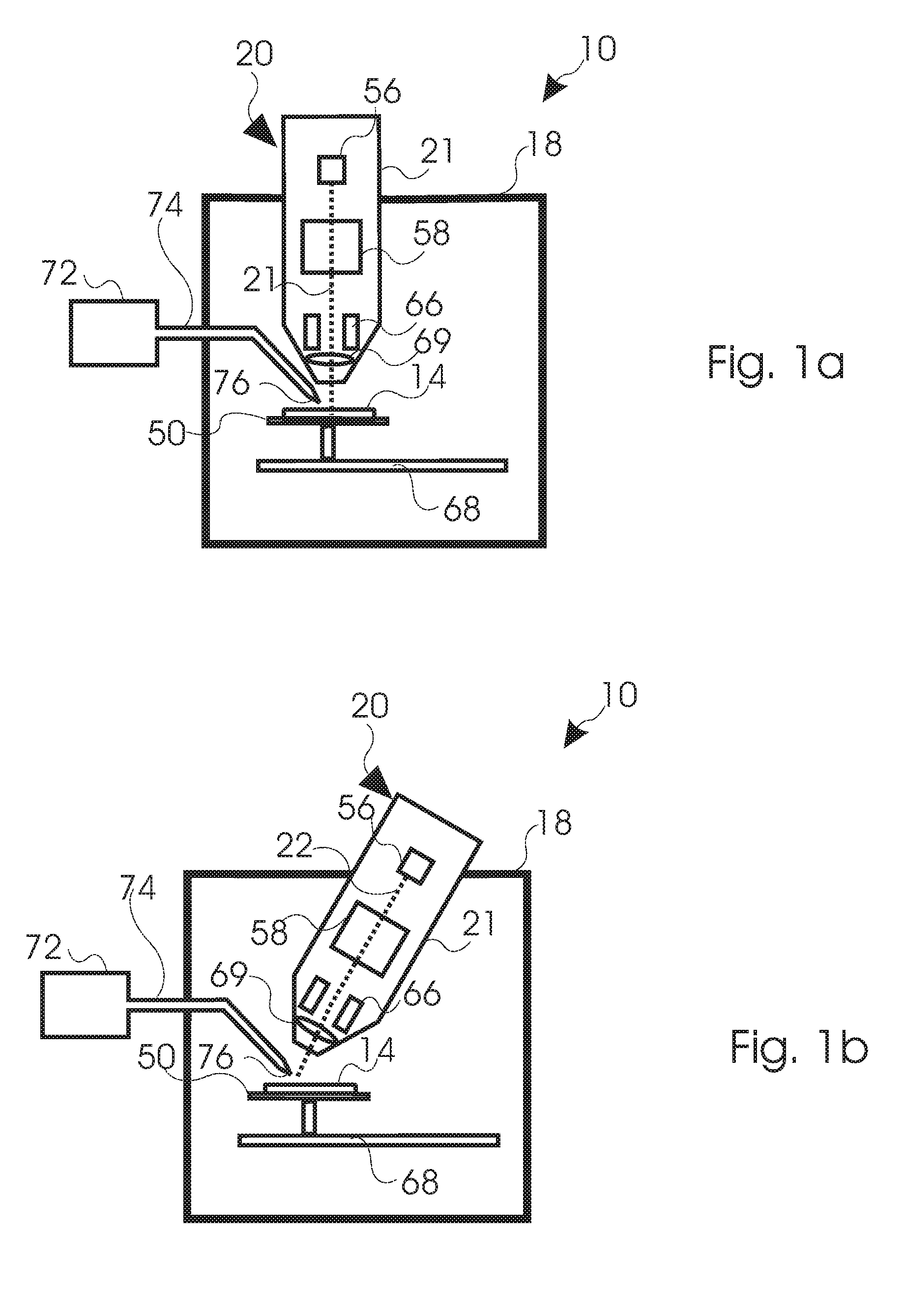
[0008]According to one embodiment an apparatus for in-situ specimen preparation is provided. The apparatus includes: a vacuum chamber for enclosing the specimen, and a ion beam device, wherein the ion beam device is connected to the vacuum chamber, the ion beam device includes: an liquid metal alloy ion source including a first element for providing a light ion species with a mass of 10 g/mol to 60 g/mol and a second element for

Problems solved by technology

Despite the progress in TEM sample preparation and TEM inspection, it is still complicated, expensive and time-consuming to carry out a TEM inspection because of the many steps needed for each measurement.
For these reasons, inspections of cross sectional thin slices of a specimen, in particular the inspection of membranes of a wafer or chip, are expensive.
Cross sectional inspections for a failure analysis of integrated circuits on a regular basis are therefore difficult.
For inspections of cross sections, layer structures and crystal structures with an SEM, problems in light of a small material contrast and sample charging may occur.
These sample preparation methods are commonly conducted separately from the manufacturing processes of the specimen and are, thus, time consuming.

Method used


Image

  • Method and apparatus for in-situ sample preparation
  • Method and apparatus for in-situ sample preparation
  • Method and apparatus for in-situ sample preparation

Examples


Embodiment Construction

[0020]Reference will now be made in detail to the various embodiments of the invention, one or more examples of which are illustrated in the figures. Each example is provided by way of explanation of the invention and is not meant as a limitation of the invention. For example, features illustrated or described as part of one embodiment can be used on or in conjunction with other embodiments to yield yet a further embodiment. It is intended that the present invention includes such modifications and variations.

[0021]Without limiting the scope of the present application, in the following it is referred to the detection of secondary electrons. The present invention can still be applied for apparatuses and components detecting secondary and / or backscattered particles in the form of electrons or ions, photons, X-rays or other corpuscles in order to obtain a specimen image. Generally, when referring to corpuscles it is to be understood as a light signal, in which the corpuscles are photons...


PUM


Abstract

An apparatus for in-situ specimen preparation is described. The apparatus includes an ion beam column 21 including at least: an liquid metal alloy ion source 56 including a first element for providing a light ion species with a mass of 10 g / mol to 60 g / mol and a second element for providing a heavy ions species with a mass of 150 g / mol or higher, a mass separator 58 for selectively separating the light ion species and the heavy ion species, and a focusing element for focusing the ion beam on a specimen. The apparatus further includes a specimen-beam-tilt unit for tilting the ion beam with respect to the specimen.

Description

FIELD OF THE INVENTION[0001]The invention relates to an apparatus and method for in-situ sample preparation of a specimen and to an apparatus and a method for inspecting an in-situ prepared specimen by means of an electron beam. In particular, the invention relates to an ion beam device including means for conducting several sample preparation steps with one ion beam column. Specifically, it relates to an apparatus for in-situ specimen preparation and a method of preparing a cross-section of a specimen.BACKGROUND OF THE INVENTION[0002]For progress in microelectronics, it is important to have tools for inspecting microelectronical structures on a chip or wafer with ever increasing spatial resolution. At the same time, it is important to decrease the costs of such inspections in order for the industry to fabricate devices of ever increasing complexity at low costs.[0003]Technologies such as microelectronics, micromechanics and biotechnology have created a high demand for structuring a...

Claims


Application Information

Patent Timeline
IPC IPC(8): G21K5/00G21K1/08G21K1/087
CPCH01J37/3056H01J2237/0245H01J2237/057H01J2237/31749H01J2237/20207H01J2237/31732H01J2237/3174H01J2237/0805
Inventor FROSIEN, JUERGEN
Owner ICT INTEGRATED CIRCUIT TESTING GESELLSCHAFT FUER HALBLEITERPRUEFTECHNIK GMBH
Learn More