RFID transceiver sensitivity focusing system

a focusing system and transceiver technology, applied in the direction of instruments, nuclear engineering, nuclear elements, etc., can solve the problems of inability to read tags, attenuation of rf field strength, and more difficult to maintain proper orientation, so as to reduce the sensitivity of rfid transceiver antennas, improve precision, and reduce the effect of sensitivity

Inactive Publication Date: 2008-08-07
INCOM CORP
View PDF13 Cites 37 Cited by
  • Summary
  • Abstract
  • Description
  • Claims
  • Application Information

AI Technical Summary

Benefits of technology

[0015]Another object of the present invention is to provide shielding which can shape an RFID shield associated with an RFID transceiver antenna to restrict RFID transceiver antenna sensitivity to a small zone.
[0016]Another object of the present invention is to provide shielding for an RFID antenna which allows the RFID antenna to be mounted inside of and near a door to accurately detect substantially all RFID circuit tags passing through the door and not detecting RFID circuit tags located outside of the doorway.
[0017]Another object of the present invention is to provide a method for enhancing the precision with which RFID transceiver antennas monitoring zones can be established; and zones to not be monitored can be precluded from sensing.

Problems solved by technology

For tracking the movement of inanimate objects, like inventory or crates, it is not difficult to maintain the tag in the proper orientation, but for humans, especially constantly moving students or employees, it is more difficult to maintain proper orientation.
This problem exists in many applications of RFID equipment in other industries.
Metal, however, has limitations, such as an undesirable ability to reflect RF electromagnetic radiation and can cause problems with ghosting of tags, and attenuating the strength of the RF field.
This can cause non-reading of tags and lower the performance and reliability of the equipment.
Known prior art RF absorption material has been found to be inadequate, as it did not control the location or focus of the RF field to a desired location.
RF absorption materials also attenuate the RF signal significantly, so that maintaining accurate tag reads is made more difficult.

Method used


Image

  • RFID transceiver sensitivity focusing system
  • RFID transceiver sensitivity focusing system
  • RFID transceiver sensitivity focusing system

Examples


Embodiment Construction

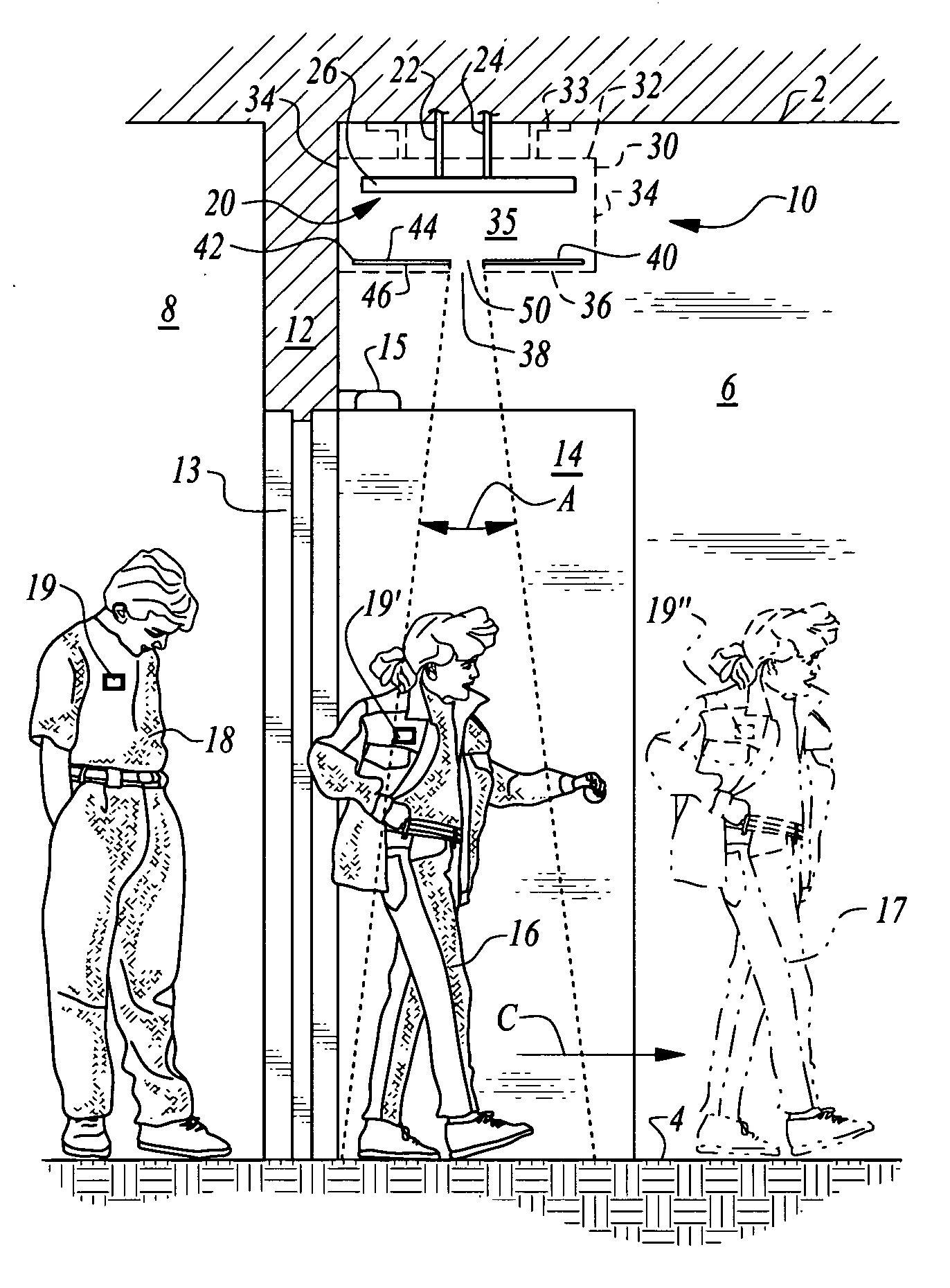
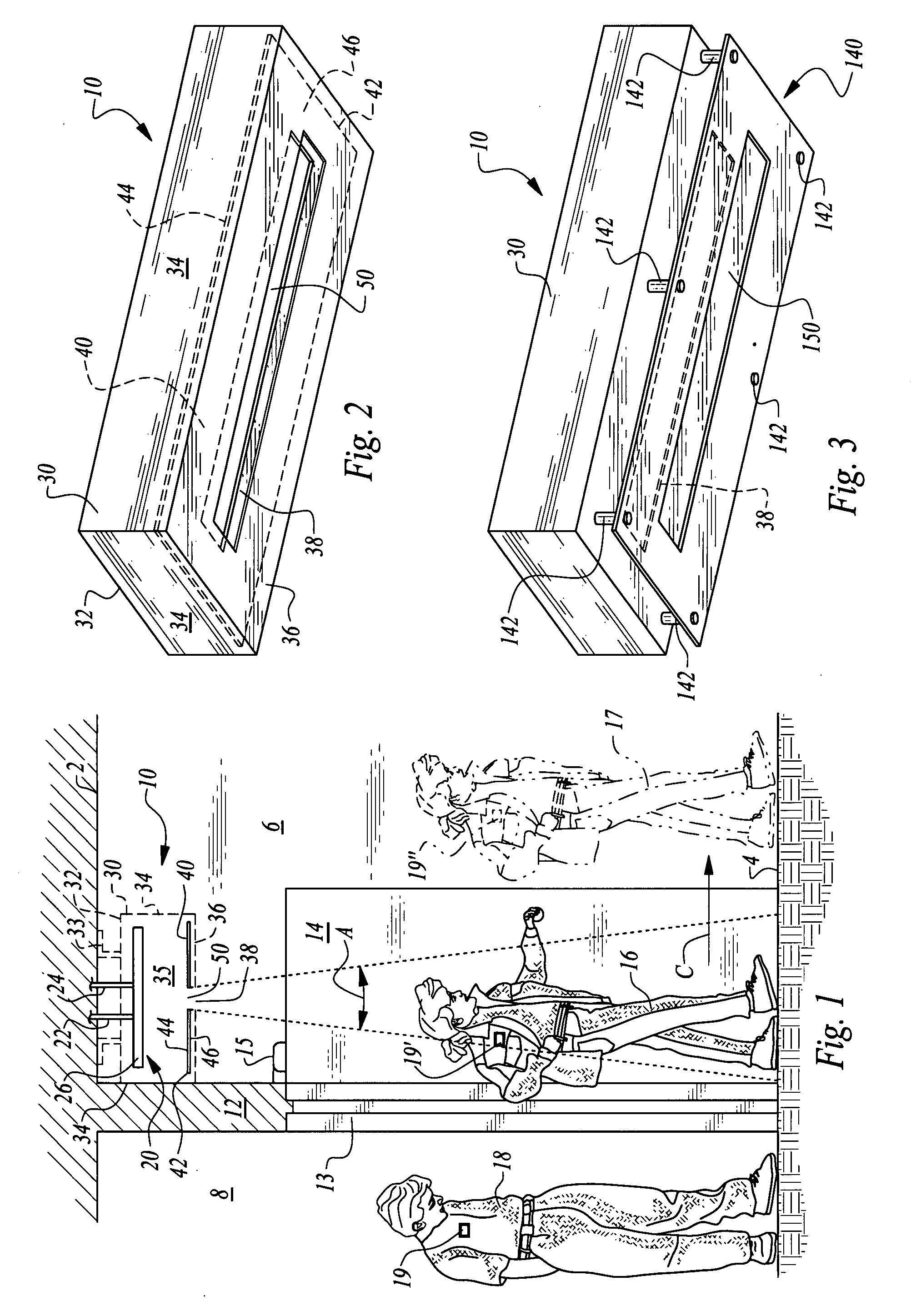
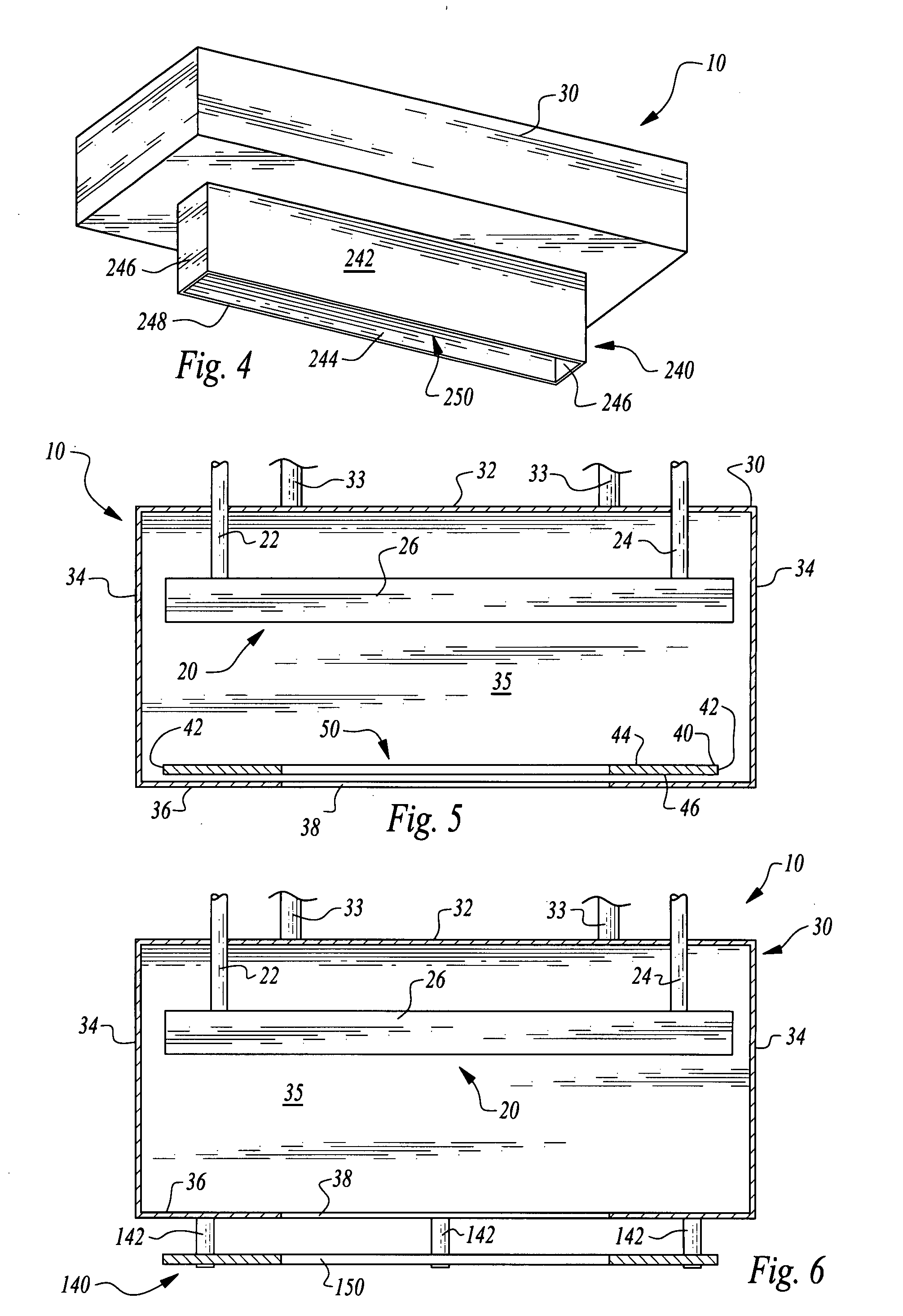
[0030]Referring to the drawings, wherein like reference numerals represent like parts throughout the various drawing figures, reference numeral 10 is directed to a system for focusing the sensitivity of an RFID transceiver. The system 10 can be utilized as part of an attendance tracking system, such as with an antenna 20 mounted above and just inside of a door 14 into a room 6 where attendance is to be tracked. With this system 10, the RF field generated by the transceiver antenna 20 is focused by shielding 40 so that attendees 16, 17 can have their associated RFID circuitry tags 19′, 19″ read while a non-attendee 18 outside of the room 6, such as in an adjacent hallway 8, who is also wearing an RFID tag 19, does not have his tag read. Such focusing of the sensitivity of the RFID transceiver antenna 20 improves the accuracy with which a variety of different RFID systems can function to record the presence or absence of RFID tags 19 within a monitoring zone.

[0031]In essence, and with...


PUM


Abstract

Shielding of a particular material and geometry is interposed between a radio frequency identification (“RFID”) antenna transceiver and a zone to be monitored by the antenna. The shielding has an aperture therein that to some extent defines a degree of focusing of the radio frequency (“RF”) field associated with the antenna. RFID tags having appropriate RFID circuitry are only detected by the antenna when they pass within the focused RF field. The shielding is formed of a thin metalized plastic material, such as film used in forming anti-static material for storage of sensitive electronics. One particular formulation is primarily polyethylene film with an aluminum coating or layer thereon.

Description

FIELD OF THE INVENTION[0001]The following invention relates to RFID transceiver antennas, and particularly to methods for focusing the sensitivity of the RFID transceiver antenna to minimize detection of portable RFID circuits located close to but outside of a monitoring zone to which the antenna is directed. The system and method of this invention can be directed to attendance monitoring systems with portable RFID circuits within tags or other holders borne by a participant or to other RFID detection systems.BACKGROUND OF THE INVENTION[0002]The applicants for the present application have previously developed an automated attendance tracking system. That system is disclosed in U.S. patent application Ser. No. 10 / 919,723, filed Aug. 16, 2004, published on Feb. 16, 2006 as Publication No. 2006 / 0035205, and the disclosure of that application is incorporated herein by reference in its entirety.[0003]Generally, this and other Radio Frequency Identification (“RFID”) systems have an RFID t...

Claims


Application Information

Patent Timeline
Patent Type & Authority Applications(United States)
IPC IPC(8): G21F1/00
CPCG06K7/10079G01D21/00
Inventor TURNER, FLORRIEAHLERS, DOUGLAS
Owner INCOM CORP
Why Eureka
Try Eureka