Method of charging double electric layer electrochemical capacitors

a capacitor and double electric layer technology, applied in capacitor collector combinations, charging/discharging current/voltage regulation, capacitor collector combinations, etc., can solve the problems of “thermal acceleration", possible reduction of the life cycle of a hes, and significant change in the thermal condition of a hes, so as to prevent excessive overheating and gassing, and rule out any overcharge

Inactive Publication Date: 2008-08-07
UNIVERSAL SUPERCAPACITORS LLC
View PDF31 Cites 9 Cited by
  • Summary
  • Abstract
  • Description
  • Claims
  • Application Information

AI Technical Summary

Benefits of technology

[0023]The present invention is directed to the controlled and optimal charging of electrochemical capacitors. A charging process of the present invention should provide, for example: an optimal or pre-assigned value of stored energy; a timely stoppage of the charging process so as to rule out any overcharge; a complete charge, irrespective of the initial state of charge; an optimal charge over the entire range of capacitor operating temperatures; prevention of excessive overheating and possible gassing via the safety valve; and compensation for losses of energy during operation of a capacitor as a back-up power source or due to self-discharge, so as to maintain the capacitor device in a state of maximum charge for a long period of time.
[0033]Charging techniques according to this embodiment of the present invention allow for the use of charging power which is randomly changing over time. This makes it possible to use inexpensive power sources in which no special technical means are used to stabilize the charge current.

Problems solved by technology

For example, while HES devices may be inferior to batteries in terms of the value of their specific weight and volume of stored energy, HES devices are significantly better than batteries in terms of life cycle, range of allowable values of charge current, and rapid charging capability.
There are, however, fundamental differences between batteries and electrochemical capacitor energy storage devices that prevent or teach against the use of identical charging process control schemes.
Furthermore, when uncontrolled charging is performed, some reduction of the life cycle of a HES is also possible.
For example, a considerable change in the thermal condition of a HES may occur when the charge rate of the HES is high.
When the stationary thermal mode is violated, there is high risk of “thermal acceleration” during which the processes of the gas cycle may be accelerated, the temperature may go up, and the charge current may increase in a spontaneous and critically fast manner.
At the same time, however, the practical task of controlling the charging process of HES devices remains unresolved.

Method used


Image

  • Method of charging double electric layer electrochemical capacitors
  • Method of charging double electric layer electrochemical capacitors
  • Method of charging double electric layer electrochemical capacitors

Examples


example 1

[0056]A capacitor module consisting of seven serially connected HES' of a PbO2|H2SO4|C system was charged. The parameters of a single HES at room temperature during the charge by a 50 A constant current in the voltage window of 2.4-0.8 V was observed to be:

capacitance180kFCoulomb capacity62Ahdelivered energy110Whimpedance (at 50 Hz frequency)1.2mOhmself-discharge current50mA

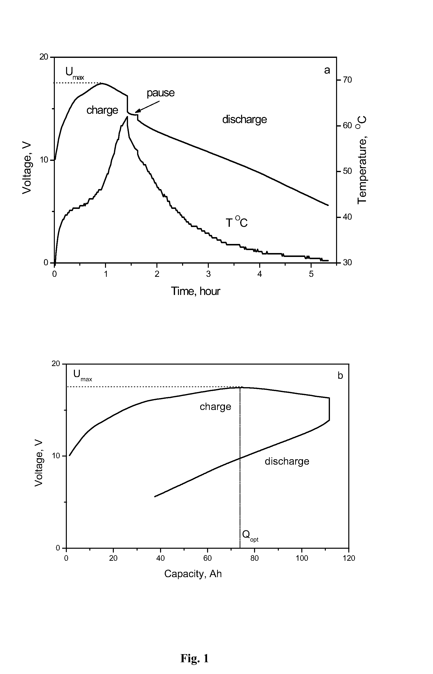
[0057]FIG. 1 shows the change in voltage and temperature of this capacitor module in the process of charge and discharge by the 50 A constant current in room temperature ambient air. As shown, the state of charge increases until the charge voltage reaches the maximum value Umax=16.8 V, whereafter it starts decreasing as charging is continued.

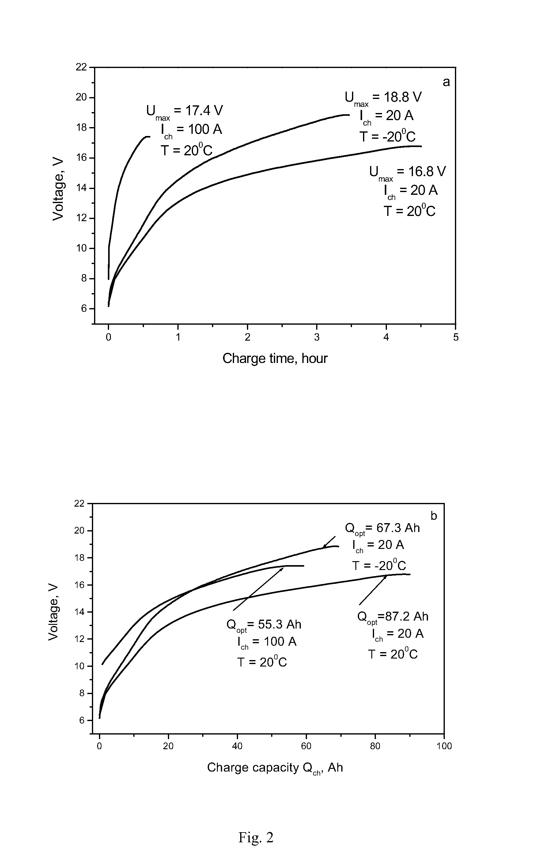
[0058]As shown in FIG. 2, when the capacitor module is charged by constant currents of different value and at different ambient air temperatures, the voltage of the capacitor module changes in a similar manner. This characteristic of the voltage behavior during the charging p...

example 2

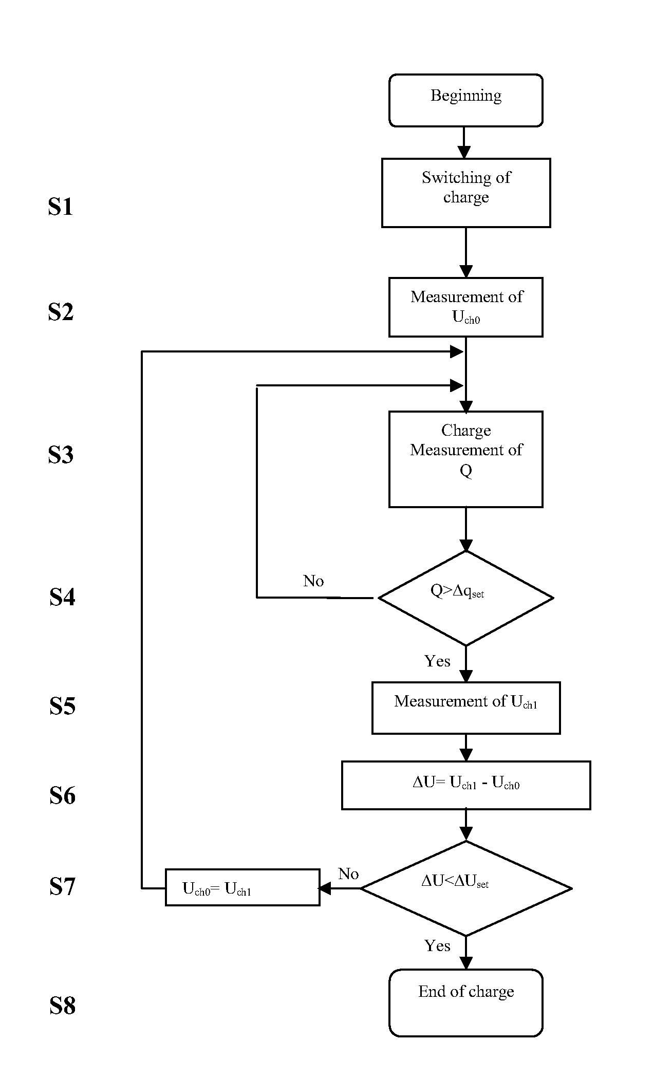
[0068]Charging of the HES module, whose design is set forth in the description of Example 1, was performed. FIG. 6 shows a block-diagram of the charger 9 used to perform said charging. A HES module 8 is again connected to the charging device 9. As shown, the charging device 9 includes a power source 10, a current sensor 11, a controller of the electricity quantity 12, a voltage controller 13, a key 14, and a pause timer 15.

[0069]This particular charging process was performed in the sequence shown in FIG. 7. The charge power changed at random during the charging process. In this particular example, the pattern of charge power variation corresponds to the change of the output power of a wind generator during a windy day in the Central region of Russia.

[0070]At the time of switching, the charger 9 gives a signal to the pause timer 15, which in its turn gives a signal to the voltage controller 13 in order to measure the initial voltage Ur0 (S9). The voltage controller 13 measures the vo...

example 3

[0075]A capacitor energy storage device based on three modules connected in parallel was charged. Each module was based on 100 serially connected HES' of a NiOOH|KOH|C system. The parameters of a single capacitor at room temperature and charged by constant current in the voltage window of 1.7-0.8 V were observed to be:

capacitance of the capacitor100kFCoulomb capacity25 ± 1Ahdelivered energy30 ± 1Whinternal resistance0.5mOhm

[0076]The charging device used in this particular example was the charging device 9 shown in FIG. 6 and described above. The power source 10 comprised: a transformer having 3-phase power supplied thereto from a 380 V industrial grid, with the consumed power at a rated charge current of not more than 100 kW; a rectifier assembly; and a pulse-phase control device. The relative error of the current stabilization was ±3%. The maximum value of the constant current was 450 A. The maximum constant voltage output was 220 V.

[0077]Digital indicators within a data entry pane...


PUM


Abstract

The present invention is directed to methods for the automatic charging of an electrochemical electrical energy storage device. Charging may be performed until a pre-assigned voltage increment value measured across the terminals of the storage device is reached. Recurrent periods of charging and rest may be employed, with measurements of voltage taken and voltage increment determined after the passage of an assigned quantity of electrical energy. Automatic completion of the charging process is provided for, irrespective of the design features and number of energy storage devices (e.g., capacitors) in a module, the initial state of charge and / or temperature of the storage device, or the value and / or time instability of the charging current.

Description

BACKGROUND OF THE INVENTIVE FIELD[0001]The present invention relates to the charging of electrochemical capacitors designed for the storage of electrical energy. More particularly, the present invention is directed to providing an effective method for charging electrochemical capacitors when the charge power changes over time, and to ensuring the timely completion of the charging process once an optimal state of charge is reached.[0002]Heterogeneous electrochemical supercapacitor (HES) energy storage devices have been increasingly used for electrical energy storage (see, e.g., U.S. Pat. No. 6,518,734 to A. Nourai, et al., entitled “System And Method Of Forming Capacitor-Based Electrical Energy Storage Modules”). Traditionally, electrical energy storage by rechargeable power sources has been dominated by storage batteries. However, various features of HES devices make their use for electrical energy storage superior to batteries. For example, while HES devices may be inferior to batt...

Claims


Application Information

Patent Timeline
Patent Type & Authority Applications(United States)
IPC IPC(8): H02J7/00
CPCH01G9/155H02J7/008H02J7/345Y02B40/90H02J7/0086H02J7/045Y02E60/13H01G11/14H01G11/08Y02B40/00H02J7/04H02J7/007182H02J7/00
Inventor STARODUBTSEV, NIKOLAI FEDOROVICHKARPOV, VLADISLAV ALEKSEEVICHDRONOV, VIKTOR ALEXANDROVICHKAZARYAN, SAMVEL AVAKOVICHKOGAN, VLADIMIR I.MILLER, JOHN R.RAZUMOV, SERGEY NIKOLAEVICHSMELKOV, ALEXANDER IVANOVICHLITVINENKO, SERGEY VITALIEVICH
Owner UNIVERSAL SUPERCAPACITORS LLC
Why Eureka
Try Eureka