Method of charging double electric layer electrochemical capacitors
a capacitor and double electric layer technology, applied in capacitor collector combinations, charging/discharging current/voltage regulation, capacitor collector combinations, etc., can solve the problems of “thermal acceleration", possible reduction of the life cycle of a hes, and significant change in the thermal condition of a hes, so as to prevent excessive overheating and gassing, and rule out any overcharge
- Summary
- Abstract
- Description
- Claims
- Application Information
AI Technical Summary
Benefits of technology
Problems solved by technology
Method used
Image
Examples
example 1
[0056]A capacitor module consisting of seven serially connected HES' of a PbO2|H2SO4|C system was charged. The parameters of a single HES at room temperature during the charge by a 50 A constant current in the voltage window of 2.4-0.8 V was observed to be:
[0057]
capacitance180kFCoulomb capacity62Ahdelivered energy110Whimpedance (at 50 Hz frequency)1.2mOhmself-discharge current50mA
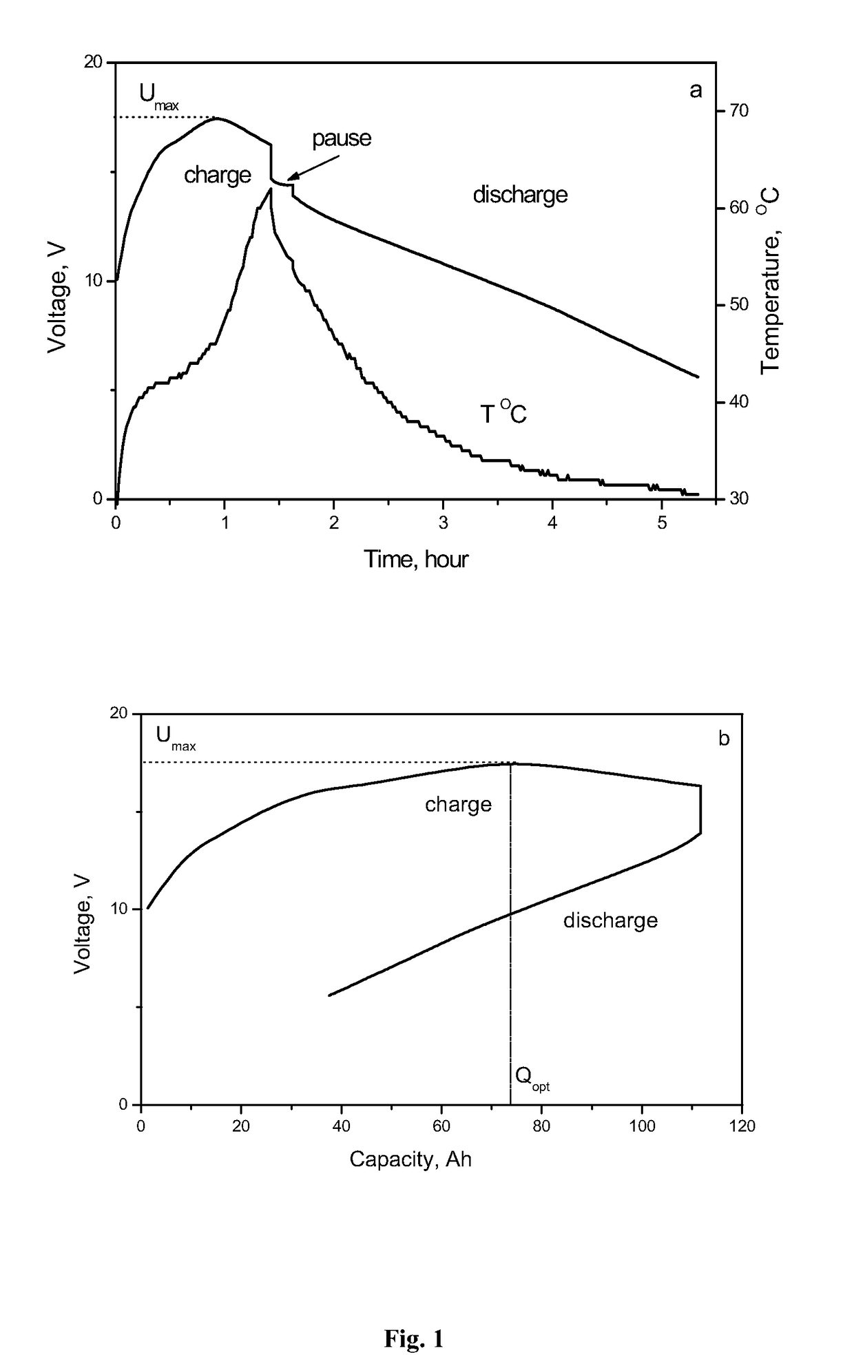
[0058]FIG. 1 shows the change in voltage and temperature of this capacitor module in the process of charge and discharge by the 50 A constant current in room temperature ambient air. As shown, the state of charge increases until the charge voltage reaches the maximum value Umax=16.8 V, whereafter it starts decreasing as charging is continued.
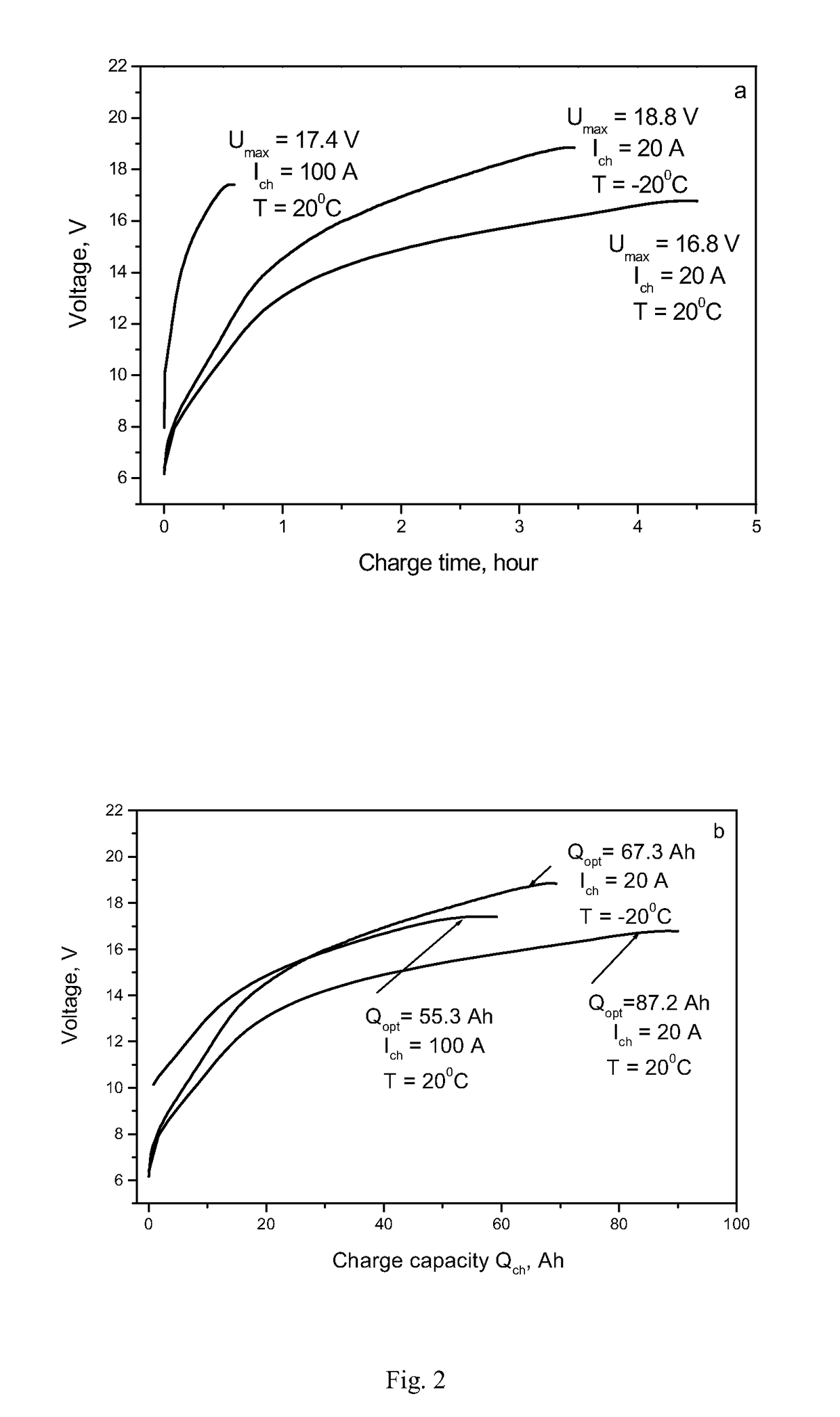
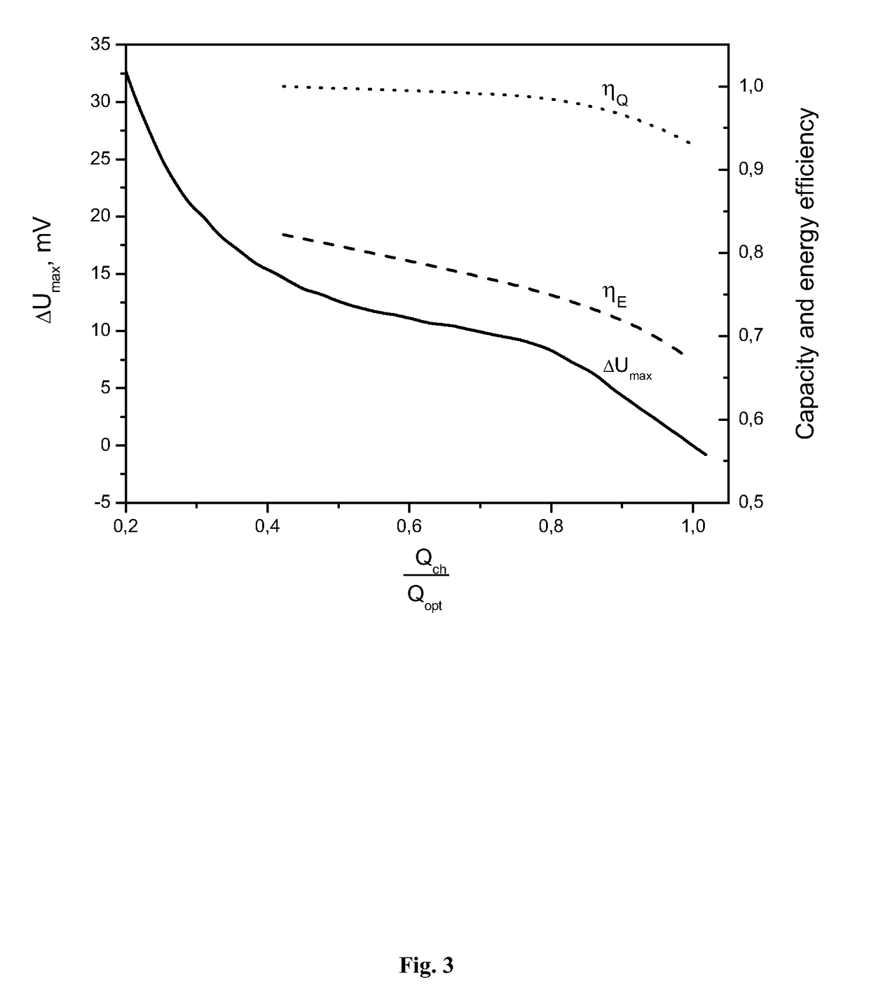
[0059]As shown in FIG. 2, when the capacitor module is charged by constant currents of different value and at different ambient air temperatures, the voltage of the capacitor module changes in a similar manner. This characteristic of the voltage behavior during the char...
example 2
[0069]Charging of the HES module, whose design is set forth in the description of Example 1, was performed. FIG. 6 shows a block-diagram of the charger 9 used to perform said charging. A HES module 8 is again connected to the charging device 9. As shown, the charging device 9 includes a power source 10, a current sensor 11, a controller of the electricity quantity 12, a voltage controller 13, a key 14, and a pause timer 15.
[0070]This particular charging process was performed in the sequence shown in FIG. 7. The charge power changed at random during the charging process. In this particular example, the pattern of charge power variation corresponds to the change of the output power of a wind generator during a windy day in the Central region of Russia.
[0071]At the time of switching, the charger 9 gives a signal to the pause timer 15, which in its turn gives a signal to the voltage controller 13 in order to measure the initial voltage Ur0 (S9). The voltage controller 13 measures the vo...
example 3
[0076]A capacitor energy storage device based on three modules connected in parallel was charged. Each module was based on 100 serially connected HES' of a NiOOH|KOH|C system. The parameters of a single capacitor at room temperature and charged by constant current in the voltage window of 1.7-0.8 V were observed to be:
[0077]
capacitance of the capacitor100kFCoulomb capacity25 ± 1Ahdelivered energy30 ± 1Whinternal resistance0.5mOhm
[0078]The charging device used in this particular example was the charging device 9 shown in FIG. 6 and described above. The power source 10 comprised: a transformer having 3-phase power supplied thereto from a 380 V industrial grid, with the consumed power at a rated charge current of not more than 100 kW; a rectifier assembly; and a pulse-phase control device. The relative error of the current stabilization was ±3%. The maximum value of the constant current was 450 A. The maximum constant voltage output was 220 V.
[0079]Digital indicators within a data entr...
PUM
 Abstract
Description
Claims
Application Information
 - R&D
- Intellectual Property
- Life Sciences
- Materials
- Tech Scout
- Unparalleled Data Quality
- Higher Quality Content
- 60% Fewer Hallucinations
Browse by: Latest US Patents, China's latest patents, Technical Efficacy Thesaurus, Application Domain, Technology Topic, Popular Technical Reports.
© 2025 PatSnap. All rights reserved.Legal|Privacy policy|Modern Slavery Act Transparency Statement|Sitemap|About US| Contact US: help@patsnap.com


