Signal Equalizer for Balanced Transmission Line-Based Video Switching

a technology of video switching and signal equalizer, which is applied in the field of signal equalizer devices, systems, and methods for shielded and unshielded twisted pairbased video switching, can solve the problems of video signal quality suffer, video switching devices are subject to signal arrival skew, and the display of video with high quality

Inactive Publication Date: 2008-08-07
MAGENTA RES
View PDF3 Cites 17 Cited by
  • Summary
  • Abstract
  • Description
  • Claims
  • Application Information

AI Technical Summary

Benefits of technology

[0010]In one embodiment of the invention, a method of equalizing signals from a plurality of balanced transmission line cables having different lengths includes providing a first cable having a first length and a second cable having a second length, the first cable coupled to a variable resistor. In the context of this description the “first” or “second” cable can be a single cable or a series of cables coupling electrical elements. A first signal is transmitted along the first cable to the variable resistor such that the first signal is attenuated to assume a first frequency domain characteristic. A second signal is transmitted along the second cable such that the second signal is attenuated to assume a second frequency domain characteristic. A volt

Problems solved by technology

However, there are a number of obstacles in displaying video with high quality.
Video switching devices are subject to signal arrival skew, which occurs when multiple channels of video are propagated through physically separate transmission lines.
Also, when a video source and display are connected through transmission lines, video signal quality suffers as the length of the transmission line increases.
Furthermore, undesirable variations in video quality will appear as the video switch selects different inputs to be displayed.
Transmission lines, such as coaxial cables, fiber optic cables, and unshielded twisted pair cables, impose losses that are manifested as attenuation and high frequency roll off, which are the combined result of ohmic, skin effect, dielectric and radiation losses.
High-resolution analog signals that contain a very broad spectrum of energy, often occupying 20 octaves or more per channel, are especially susceptible to attenuation and roll off even in moderately long cables.
Visually, cable losses are manifested as horizontal aperture distortion (smearing) and a loss of fine detail resolution.
However, these cables are both costly and cumbersome, often requiring the installation of as many

Method used


Image

  • Signal Equalizer for Balanced Transmission Line-Based Video Switching
  • Signal Equalizer for Balanced Transmission Line-Based Video Switching
  • Signal Equalizer for Balanced Transmission Line-Based Video Switching

Examples


Embodiment Construction

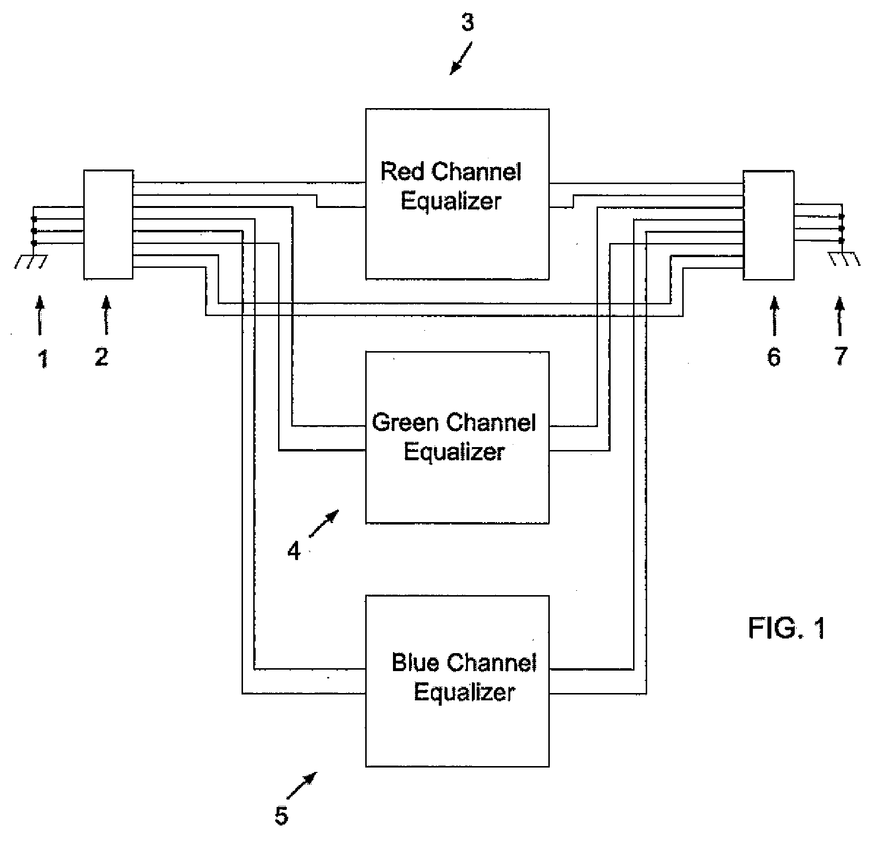
[0019]FIG. 1 is a block diagram of one embodiment of a signal equalizer. An input signal is received from UTP cable 1 into RJ-45 input jack 2. The UTP cable 1 contains the high resolution analog video signal. Each of the red, green and blue color signals is transmitted along one of the four twisted pair lines. The fourth twisted pair in the UTP cable is used for auxiliary signals and does not undergo signal processing and is simply passed through the equalizer. The red, green and blue channel signals are ported to their respective color channel equalizers 3-5, where they are equalized as described below. After equalization, the signals are outputted at RJ-45 output jack 6 to UTP cable 7. The structure of the red, green and blue channel equalizers 3-5 are identical. For the sake of clarity, only the operation of the red channel equalizer 3 will be discussed in detail, since the green and blue channel equalizers operate in the same manner.

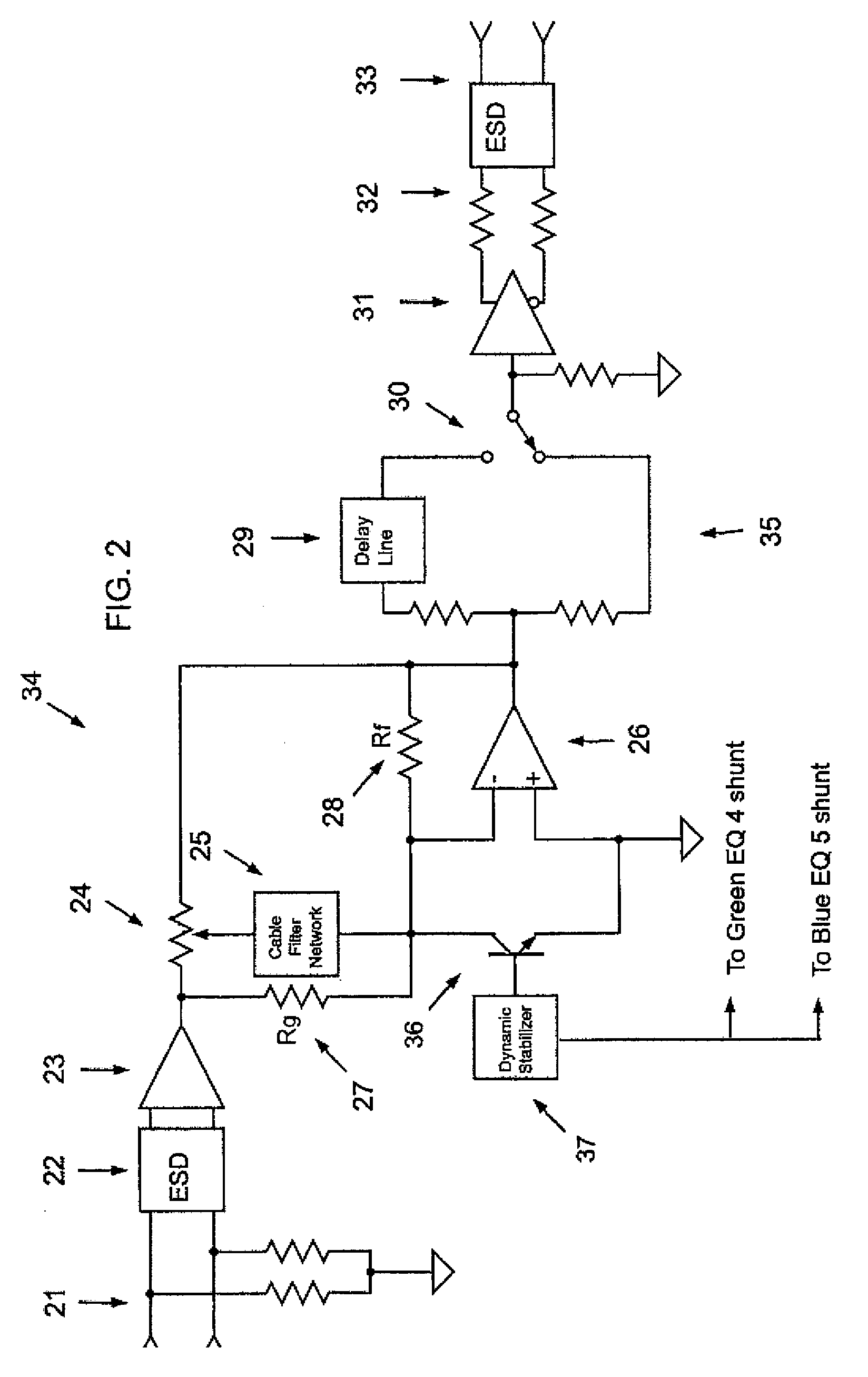
[0020]As shown in FIG. 2, when the signal is r...


PUM


Abstract

A method of equalizing signals from a plurality of balanced transmission line cables having different lengths includes providing a first cable having a first length and a second cable having a second length, the first cable coupled to a variable resistor. A first signal is transmitted along the first cable to the variable resistor such that the first signal is attenuated to assume a first frequency domain characteristic. A second signal is transmitted along the second cable such that the second signal is attenuated to assume a second frequency domain characteristic. A voltage of the first signal is divided in the variable resistor such that the first signal assumes substantially the second frequency domain characteristic. The first signal having the second frequency domain characteristic is outputted.

Description

BACKGROUND OF THE INVENTION[0001]1. Field of the Invention[0002]The present invention relates to video switching equipment, and in particular, to a signal equalizer device, system, and method for shielded and unshielded twisted pair-based video switching.[0003]2. Description of Related Art[0004]A video switch allows a user to route a plurality of video source inputs to a single or plurality of video displays. Video switching is typically performed by centralized equipment having input and output ports through which video signals interface. However, there are a number of obstacles in displaying video with high quality. Video switching devices are subject to signal arrival skew, which occurs when multiple channels of video are propagated through physically separate transmission lines. Also, when a video source and display are connected through transmission lines, video signal quality suffers as the length of the transmission line increases. In a video switching environment, input sign...

Claims


Application Information

Patent Timeline
IPC IPC(8): H04N5/268
CPCH04N5/268H04N5/44H04N9/68
Inventor MILLER, CHRISMORTENSEN, KEITH
Owner MAGENTA RES
Why Eureka
Try Eureka