Grounded rotating anode x-ray tube housing

a rotating anode and x-ray tube technology, applied in the field of medical x-ray tubes, can solve the problems of poor reliability and small assembly size, and achieve the effect of simplifying the tube design a great deal

Inactive Publication Date: 2008-08-07
GRADY JOHN K
View PDF6 Cites 12 Cited by
  • Summary
  • Abstract
  • Description
  • Claims
  • Application Information

AI Technical Summary

Benefits of technology

[0016]This new configuration allows the cathode plug to be moved virtually totally inside the housing. The cathode plug can physically almost touch the center section of the x-ray tube (i.e., which can be glass or, preferably, metal). This results in a minimal size of the assembly and a single cable that exits parallel to the long axis.
[0017]The invention also eliminates the rather difficult to achieve 75 kV insulation now required in bipolar designs between the anode motor coil and metal center (which are both essentially grounded) and the anode terminal which is at 75 kV in present designs. This is a source of failure and poor reliability that is eliminated; no insulation is needed in the new configuration, which simplifies the tube design a great deal.
[0018]Prior rotating x-ray tubes have used two rubber-coated cables, each capable of handling up to 75 kV, connected tangentially at the anode and cathode ends of the tubes, one at each end. That prevented stiffness problems with the prior rubber coating needed for handling 150 kV. New advanced cable insulation technology (i.e., EPR) allows for a single cable, instead of the two bulky ones, where the single cable can now carry 150 kV and remain flexible.

Problems solved by technology

This results in a minimal size of the assembly and a single cable that exits parallel to the long axis.
This is a source of failure and poor reliability that is eliminated; no insulation is needed in the new configuration, which simplifies the tube design a great deal.

Method used


Image

  • Grounded rotating anode x-ray tube housing
  • Grounded rotating anode x-ray tube housing
  • Grounded rotating anode x-ray tube housing

Examples


Embodiment Construction

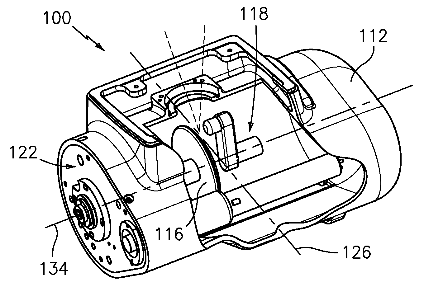
[0036]Referring to FIGS. 4A, 4B, 4C, 4D and 4E, Applicant's preferred embodiment 100 of a “GROUNDED ROTATING ANODE X-RAY TUBE HOUSING” is shown in detail. Applicant's preferred embodiment is an arrangement of a purchased pre-designed rotating anode x-ray tube but having a unique mechanical arrangement for a high voltage (“HV”) cable in a lead-lined housing of specific design / features.

[0037]Applicant's preferred tube 100 is a bipolar tube, as all tubes are, with a single-end terminal connection which includes a metal shell or housing 112, preferably aluminum, lined with lead. Housing 112 contains a rotating anode x-ray tube 114 insert (i.e., Model G-1092 manufactured by Varian Medical Systems, Inc.) with a rotating anode disk 116 and an adjacent cathode 118; and, an extended Federal Standard receptacle 120 (rated up to 160 kV), such as the type manufactured by Claymount Assemblies B.V. Both the anode insert 114 and receptacle 120 are mounted on an anode end 122 of the housing. The an...


PUM


Abstract

An improved rotating anode x-ray tube housing is disclosed. In the preferred embodiment: a single cable, insulated with Ethylene-Propylene Rubber (“EPR”), has an extended Federal Standard terminal or plug mounted within an extended Federal Standard receptacle, attached to an anode end of the housing; the cable is designed to carry up to approximately 150 kV to power the cathode; and insulation of the plug also insulates the 150 kV from a grounded center portion of the x-ray tube and the anode disk area. The longitudinal axes of the anode and high-voltage plug are parallel to one another. This new configuration allows the cathode plug and receptacle to be moved virtually entirely inside the housing. This results in absolute minimal size of the assembly, and a single cable that exits parallel to the rotational axis of the housing.

Description

FIELD OF INVENTION[0001]The present invention relates in general to medical x-ray tubes. More particularly, it relates to rotating anode x-ray tube housings carrying high voltage (“HV”).BACKGROUND[0002]Most x-ray generating devices operate in similar fashion. X-rays are produced in a vacuum tube housing or “tube” where electrons are emitted, accelerated, and then deposited upon a material of a particular composition. This process takes place, for example, within a grounded rotating anode x-ray tube comprising a vacuum, a cathode, and an anode. The cathode, when heated by an electrical current supplied by a high voltage, emits a stream of electrons. Due to an electrical potential difference across the anode and the cathode, the electrons are accelerated and impinge upon the anode, thus producing the x-rays upon impact.[0003]Since the initial clinical use of diagnostic, general purpose medical x-ray tubes, the high voltage applied to the tube housing generally has been applied equally...

Claims


Application Information

Patent Timeline
Patent Type & Authority Applications(United States)
IPC IPC(8): H01J35/10
CPCH05G1/08H05G1/04
Inventor GRADY, JOHN K.
Owner GRADY JOHN K
Why Eureka
Try Eureka