Roll machining apparatus

a technology of rolling machining and rolling bearings, which is applied in the direction of mechanical equipment, manufacturing tools, and roller bearings, etc., can solve the problems of scuffing in the bearing, the workpiece cannot be supported stably, and the bearing cannot absorb the thermal expansion of the roll in the length, so as to simplify the construction of the apparatus, enhance processing precision, and simplify the effect of the apparatus

Active Publication Date: 2008-08-07
TOSHIBA MASCH CO LTD
View PDF5 Cites 3 Cited by
  • Summary
  • Abstract
  • Description
  • Claims
  • Application Information

AI Technical Summary

Benefits of technology

[0011]According to the present invention, the first spindle of the two spindles that support the both ends of a roll is thus supported by the hydrostatic bearings both in the radial direction and in the thrust direction, while the second spindle is supported by the hydrostatic bearing in the radial direction and by the floating thrust, capable of selectively limiting axial movement of the second spindle, in the thrust direction. This enables a simple construction of the apparatus and, in addition, enables thermal expansion of the roll in the length direction, e.g. due to a change in room temperature, to be absorbed by the floating thrust while accurately supporting the roll with the hydrostatic radial bearings for the first and second spindles and with the hydrostatic thrust bearing for the first spindle, thus enhancing the processing precision.
[0012]The floating thrust is to fix the axial position of the second spindle at a predetermined position with respect to the spindle head body at the time of attaching or detaching a roil to or from the first and second spindles, and to perform initial setting of the axial position of the second spindle with respect to the spindle head body. Thus, the flowing thrust does not necessarily use a hydrostatic thrust bearing. The use of a ball bearing for the floating thrust can further simplify the construction of the apparatus and can also reduce the cost.

Problems solved by technology

However, when a spindle is supported by a hydrostatic thrust bearing which receives a thrust load, because of small bearing gap of the bearing, the bearing cannot absorb thermal expansion of a roll in the length direction e.g. due to a change in room temperature, especially when the roll has a large length, causing scuffing in the bearing.
Though the disclosed method makes it possible to absorb thermal expansion of a workpiece in the length direction e.g. due to a change in room temperature, involves a complicated structure of the apparatus.
In addition, since one end of the workpiece is not directly fixed to the spindle, but fixed to the spindle indirectly via the piston, the workpiece cannot be supported stably, and shaking, displacement of the axis, etc. of the workpiece during its rotation are likely to occur.

Method used


Image

  • Roll machining apparatus
  • Roll machining apparatus
  • Roll machining apparatus

Examples


Embodiment Construction

[0016]The present invention will now be described in detail with reference to the drawings.

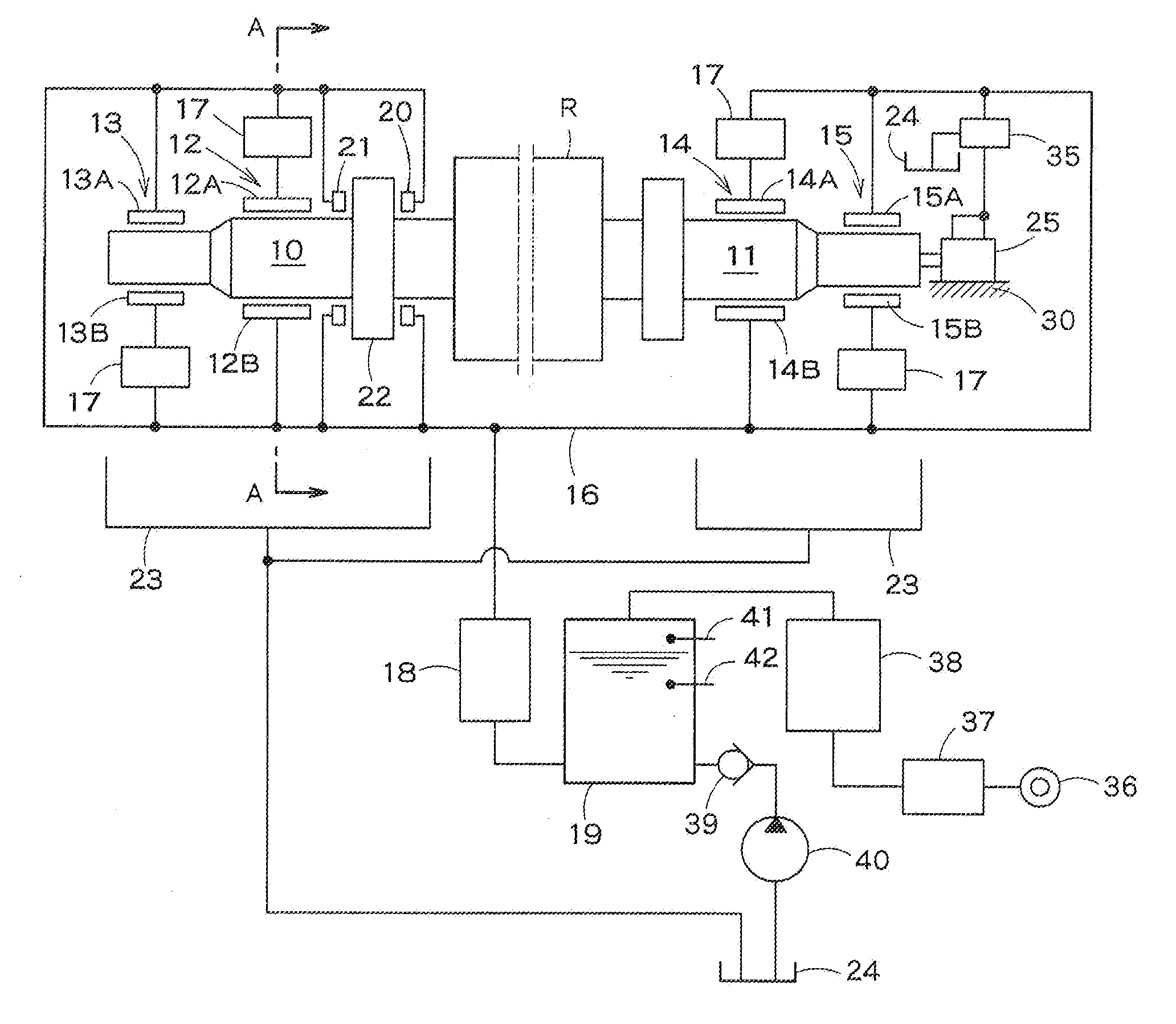
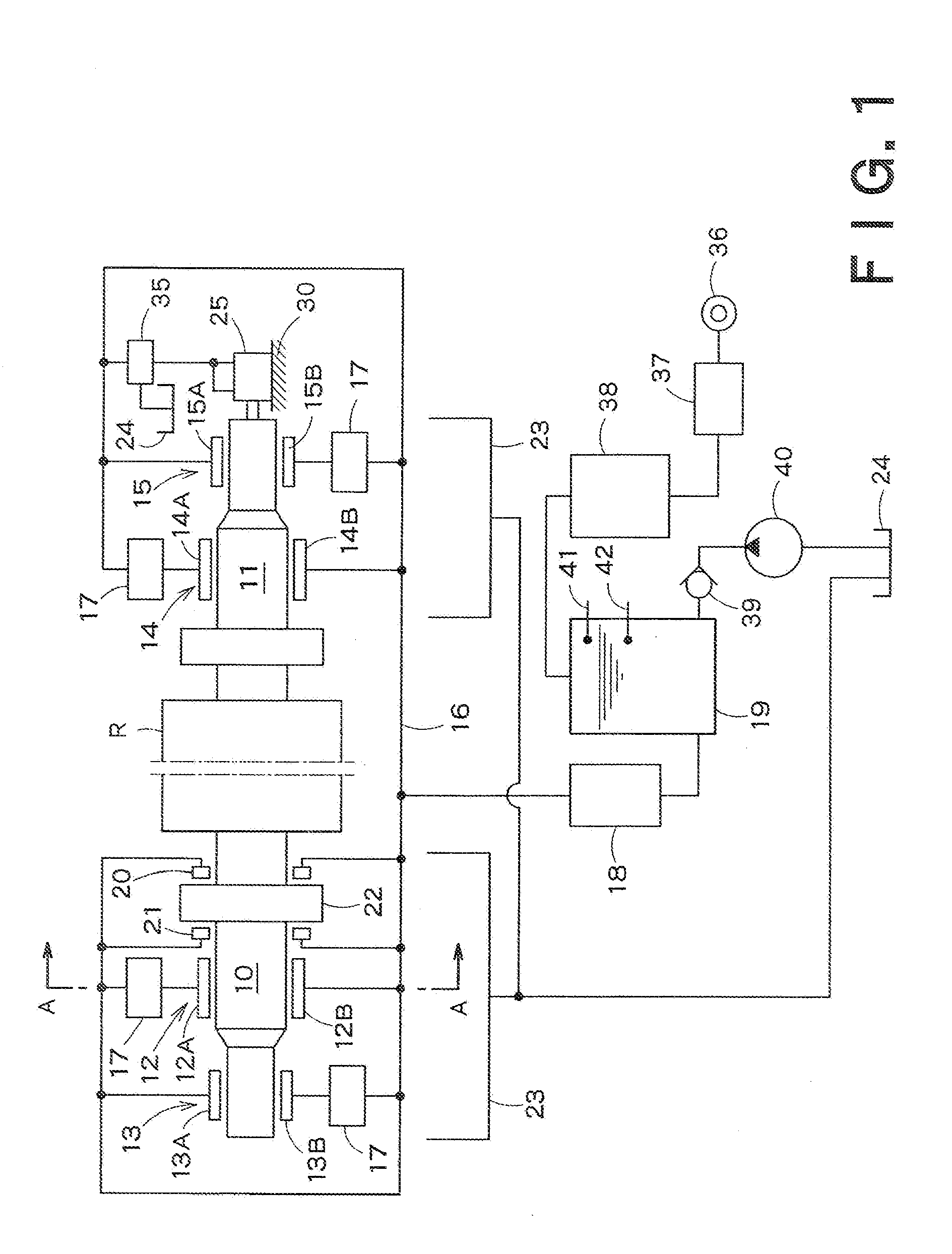
[0017]FIG. 1 shows a roll machining apparatus according to an embodiment of the present invention. In FIG. 1, R denotes a roll to be machined, and reference numerals 10 and 11 denote a first spindle and a second spindle, respectively. The first and second spindles 10, 11 are disposed opposite to each other on the same horizontal axis, and detachably fix and support the both ends of the roll R and hold the roll in a horizontal position.

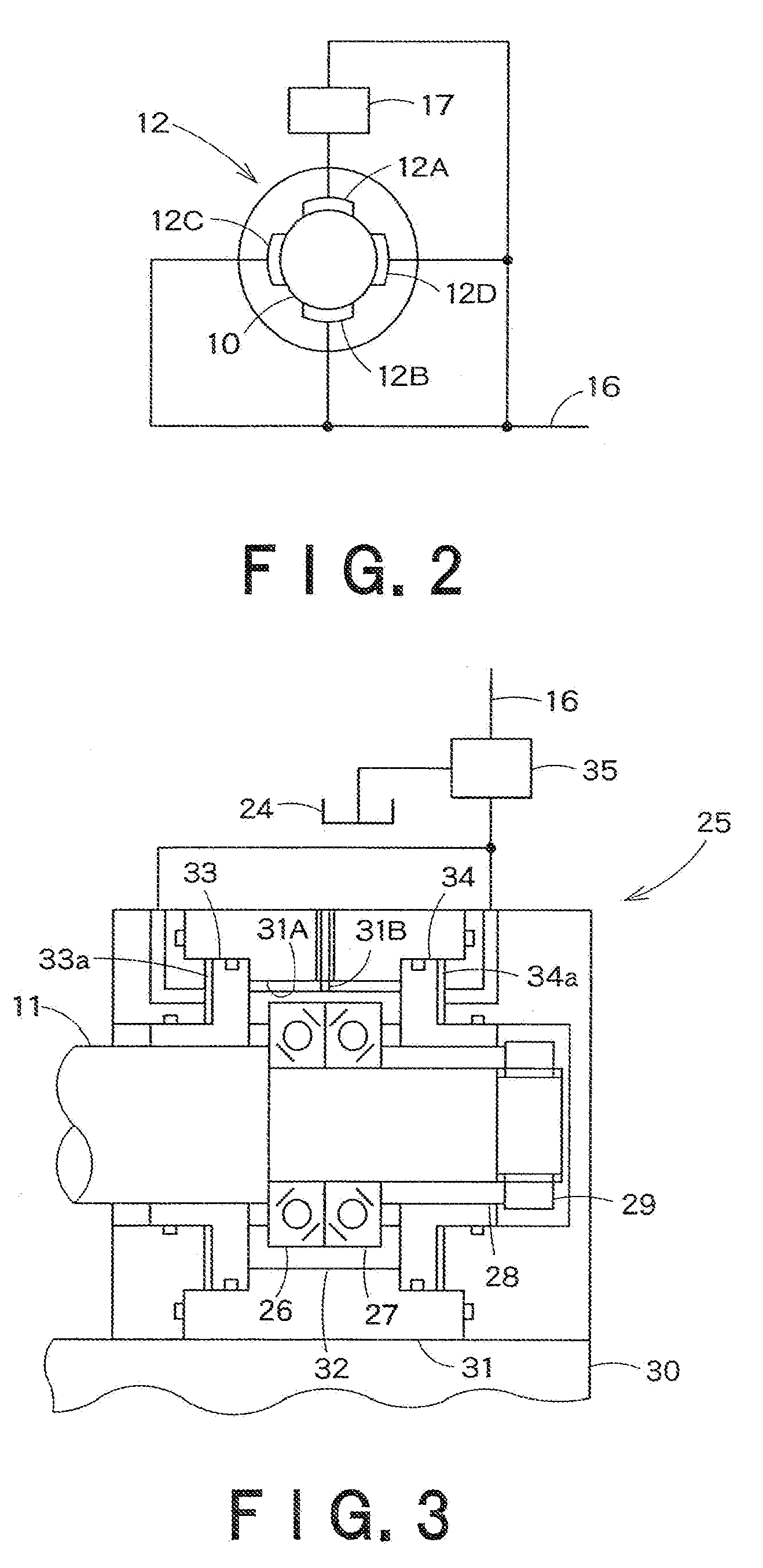
[0018]The first spindles 10, on their front and rear sides with respect to the roll R, is rotatably supported by first hydrostatic radial bearing which includes hydrostatic pocket member 12, 13. The second spindles 11, on their front and rear sides with respect to the roll R, is rotatably supported by second hydrostatic radial bearing members which includes hydrostatic pocket members, 14, 15. The hydrostatic pocket member 12, for example, has hydrostatic pockets ...


PUM

PropertyMeasurementUnit
axial movementaaaaaaaaaa
flow rateaaaaaaaaaa
temperatureaaaaaaaaaa

Abstract

There is provided a roll machining apparatus which can accurately support a roll by means of hydrostatic bearings while absorbing thermal expansion of the roll in the length direction e.g. due to a change in room temperature, thus enhancing the machining precision. The roll machining apparatus for machining the surface of a roll while supporting and rotating the roil in a horizontal position, includes: a first spindle to be detachably coupled to one end of the roll; a second spindle, disposed opposite to the first spindle on the same axis, to be detachably coupled to the other end of the roll; a first hydrostatic radial bearing for receiving the radial load of the first spindle and rotatably supporting the first spindle; a hydrostatic thrust bearing for receiving the thrust load of the first spindle and limiting axial movement of the first spindle, a second hydrostatic radial bearing for receiving the radial load of the second spindle and rotatably supporting the second spindle; and a floating thrust having a thrust bearing for receiving the thrust load of the second spindle, said thrust being capable of selectively limiting and permitting axial movement of the thrust bearing.

Description

BACKGROUND OF THE INVENTION[0001]1. Field of the Invention[0002]The present invention relates to a roll machining apparatus for machining the surface of a roll while supporting and rotating the roll in a horizontal position, and more particularly to a roll machining apparatus for machining a roll into a machined product which requires precision machining, such as a roll mold for the production of, for example, an optical film for use in a liquid crystal display or a lenticular lens for use in a rear projection device.[0003]2. Background Art[0004]A roll mold as described above requires fine, very high-precision machining. Therefore, when machining a roll into such a roll mold, it is necessary to precisely support the roll while suppressing shaking, displacement of the axis, etc. of the roll during its rotation. For this purpose, it is preferred to support spindles, supporting the both ends of the roll, by means of hydrostatic bearings.[0005]However, when a spindle is supported by a h...

Claims


Application Information

Patent Timeline
Patent Type & Authority Applications(United States)
IPC IPC(8): F16C33/10B23B19/02F16C19/10
CPCB23B5/08Y10T82/2562F16C32/06F16C13/02B23B23/04
Inventor AKIYAMA, TAKANOBU
Owner TOSHIBA MASCH CO LTD
Why Eureka
Try Eureka