Ventilation airflow rate control

a technology of airflow rate and ventilation airflow, which is applied in the direction of machines/engines, lighting and heating apparatus, heating types, etc., can solve the problems of reducing energy efficiency, reducing energy consumption, and reducing noise, so as to reduce energy consumption, reduce noise, and avoid insufficient or excessive airflow. the effect of the ra

Active Publication Date: 2008-08-07
NORTEK GLOBAL HVAC
View PDF99 Cites 90 Cited by
  • Summary
  • Abstract
  • Description
  • Claims
  • Application Information

AI Technical Summary

Benefits of technology

[0007]Various embodiments provide equipment, systems, and methods that are reasonably inexpensive, utilize existing components to at least some degree, are reasonably reliable, and can reasonably be placed into service by typical installation personnel, for example, typical service personnel in residential installations. Further still, particular embodiments provide equipment, systems, and methods that maintain (at least to some extent) cooling or heating effectiveness (or both) over a range of varying ductwork airflow restriction, that provide for reduced energy consumption in comparison with certain alternatives, that provide for reduced noise, that avoid insufficient or excessive airflow rates, that provide for sufficient airflow through evaporator coils to prevent frost formation, that continuously compensate for variations in airflow restriction, or a combination thereof, as further examples.

Problems solved by technology

However, different buildings with different ductwork have had varying amounts of airflow restriction, and prior art HVAC units installed in such systems have often provided too much or too little flow in installations where the ductwork provided more or less airflow restriction than the HVAC designers had anticipated.
In installations where airflow restriction significantly exceeded what the designers had anticipated, actual airflow rates have been insufficient, resulting in reduced energy efficiency as a result of reduced transfer of heat, inadequate heating or cooling of the space, higher utility bills than expected, frost formation on evaporator coils, or a combination thereof, as examples.
On the other hand, in installations where airflow restriction has been significantly less than what the designers anticipated, HVAC units have produced more noise than desired, consumed more fan energy than necessary, provided excessive airflow to the space causing excessive air movement within the space, or a combination thereof, as further examples.
However, this has typically required the attention of skilled personnel who have measured airflow rates using handheld instruments such as Pitot tubes, measured airflow rates at registers, performed calculations, or a combination thereof, for example.
In many installations, technicians of the necessary skill level are not available for this purpose or would add too much cost to the expense of installing and commissioning an HVAC unit.
Further, prior art systems that provided for compensating for variations in airflow restriction within HVAC ductwork typically required specialized measurement equipment for measuring airflow rates directly, for example, which added cost and complexity to HVAC systems and, at least in some cases, reduced reliability of HVAC systems.
Further, prior art systems did not operate continuously and therefore did not compensate for changes in airflow restriction that occurred after the system was commissioned, such as partial clogging of filters, user adjustment of registers, and modifications to the ductwork, as examples.

Method used


Image

  • Ventilation airflow rate control
  • Ventilation airflow rate control
  • Ventilation airflow rate control

Examples


Embodiment Construction

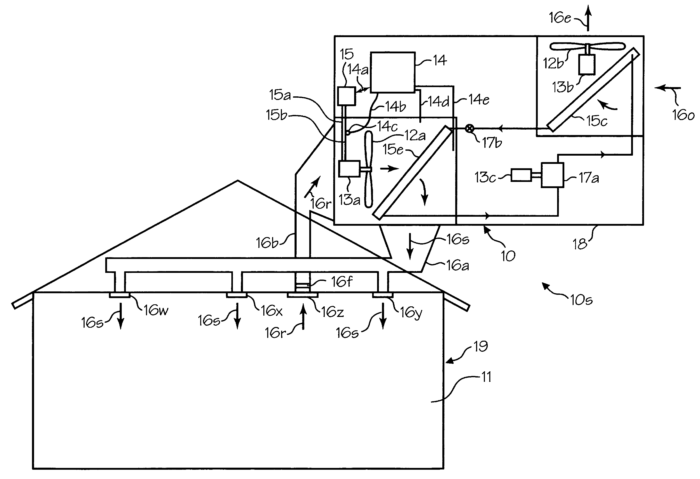
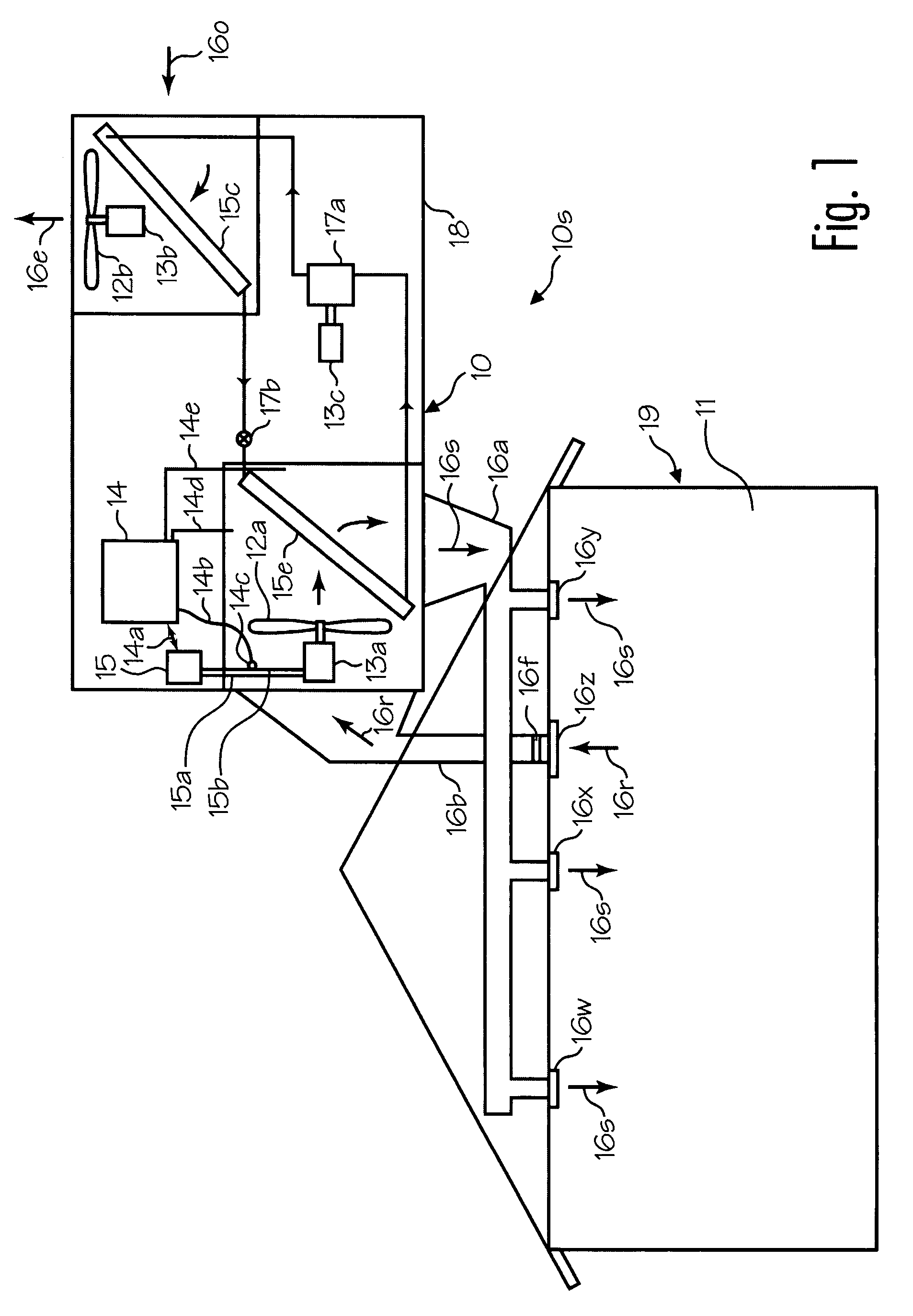
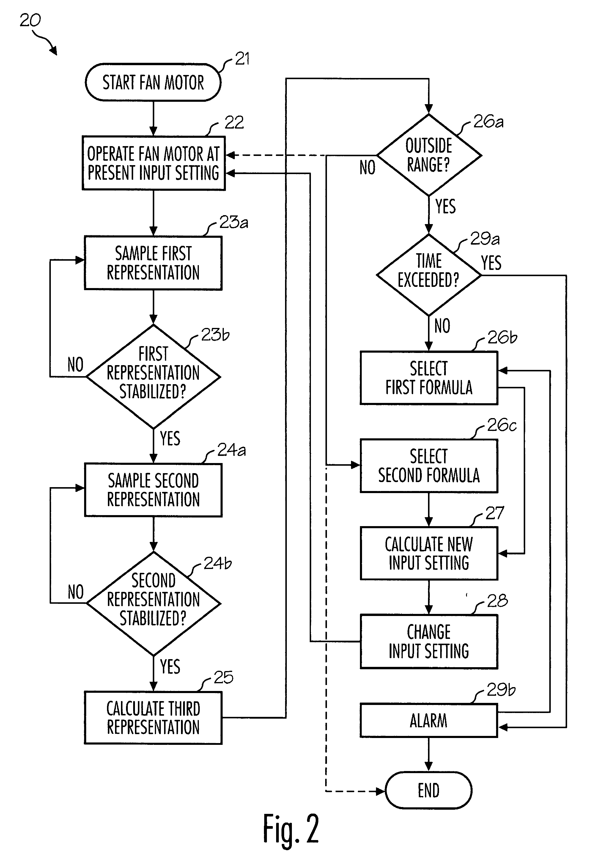
[0006]This invention provides, among other things, air handling units for ventilating an at-least partially enclosed space, air-conditioning units, methods of controlling an airflow rate within a ventilation system, and methods of providing more-constant performance of air conditioning units, as examples. Different embodiments adjust or vary speed or torque of a blower or fan motor based on inputs such as electric current of the motor or pressure (e.g., absolute or differential pressure) within the system, and speed or torque of the motor. Various embodiments of the invention provide as an object or benefit that they partially or fully address one or more of the needs, potential areas for improvement or benefit, or functions described herein, for instance. Specific embodiments provide as an object or benefit, for instance, that they at-least partially provide for control of airflow rates within ventilation systems, provide HVAC equipment, systems, and methods that provide for some d...


PUM


Abstract

Airflow rates within a ventilation system are controlled using motor speed or torque and motor electric current or pressure. Fan speed or torque may be varied to compensate for differing restriction in ductwork, and may provide a constant airflow rate over a range of varying airflow restriction. Air handlers or air conditioning units may be mass produced in common configurations, and installed in different buildings or structures with different ductwork configurations. Methods operate a fan motor at a present speed or torque, sample speed or torque, sample current of the fan motor or pressure within the ventilation system, calculate a present airflow rate within the ventilation system, calculate a new input setting using the present airflow rate and a target airflow rate, change the speed or torque to the new input setting, and repeat these steps to converge on the target airflow rate, often avoiding overshoot.

Description

FIELD OF INVENTION[0001]This invention relates to heating, ventilating, and air-conditioning (HVAC) equipment, systems and methods, and to control equipment, systems, and methods, and specific embodiments relate to mass-produced air conditioning units, for example, for residential applications, and to their controls.BACKGROUND OF THE INVENTION[0002]Heating, ventilating, and air-conditioning (HVAC) systems have been used to ventilate and maintain desirable temperatures within spaces such as buildings, and other at-least partially enclosed spaces have been equipped with ventilation systems including HVAC systems to provide comfortable and safe environments for occupants to live and work, for example. HVAC equipment and units such as air handlers, air conditioning units, heat pumps, furnaces, and the like have been mass produced in a variety of sizes and configurations, and appropriate sizes have been selected to be installed in various buildings having different or unique HVAC ductwor...

Claims


Application Information

Patent Timeline
Patent Type & Authority Applications(United States)
IPC IPC(8): F24F11/04
CPCF04D27/004Y02B30/746F24F11/0079F24F11/77Y02B30/70
Inventor CHEN, JIEHERZON, AARON D.REIFEL, ALLAN J.CHEN, YI
Owner NORTEK GLOBAL HVAC
Why Eureka
Try Eureka