Medical device delivery sheath

a technology for medical devices and sheaths, applied in the field of sheaths, can solve the problems of limited stiffness and/or flexibility of tools and implants, and difficulty in activity, and achieve the effect of facilitating the collapse and resheathing of medical devices

Inactive Publication Date: 2008-08-07
BOSTON SCI SCIMED INC
View PDF53 Cites 685 Cited by
  • Summary
  • Abstract
  • Description
  • Claims
  • Application Information

AI Technical Summary

Benefits of technology

[0007]The present invention provides a sheath having the advantages of the prior art while including the added features of controlled bending combined with radially expandability of the tip to facilitate the collapse and resheathing of a medical device.
[0008]The invention also provides catheter or sheath having a distal tip segment requiring a lower force to expand the distal tip, thus reducing the stress and axial compression forces associated with sheathing or resheathing an implant.
[0009]The invention provides a medical device delivery sheath having one or more of the following features: Sufficient axial stiffness to enable advancement of the sheath through the vasculature; sufficient bending compliance to permit movement of the sheath through bends in the vasculature; sufficient axial stiffness to enable the application of a sheathing force to collapse an expandable device into the distal end of the sheath; and distal end features that accomplish sheathing of the expandable device without harm to the device or delivery tool.
[0010]One aspect of the invention provides a catheter with a radially expandable tip. The tip has a cuff with a first end and a second end distal to the first end and a polymer jacket surrounding the cuff. The second end of the cuff has a plurality of irregular tabs. The cuff and the polymer jacket are adapted to allow the second end of the cuff to expand more easily than the first end of the cuff in response to an axially directed force on the tip of the catheter.
[0014]Yet another aspect of the invention provides a system for endovascular replacement of a heart valve. The system has a handle, a deployment tool attached to the handle, a replacement heart valve and a sheath. The deployment tool has one or more actuation elements extending therethrough. The replacement heart valve is releasably engaged to the deployment tool. The sheath extends substantially over the length of the deployment tool and replacement heart valve and has a support member with a first zone of uniform stiffness, the first zone extending substantially over the entire length of the deployment tool; and a second zone of variable stiffness, the second zone forming a distal tip of the sheath, and capable of expansion to form a funnel for assisting in the capture of the replacement heart valve.

Problems solved by technology

The diameter of the access lumen limits the diameter of such tools and implants which, among other effects, may limit the stiffness and / or flexibility of the tools and implants.
This activity could be difficult in situations in which a relatively high force is required to collapse the expanded device.

Method used


Image

  • Medical device delivery sheath
  • Medical device delivery sheath
  • Medical device delivery sheath

Examples


Embodiment Construction

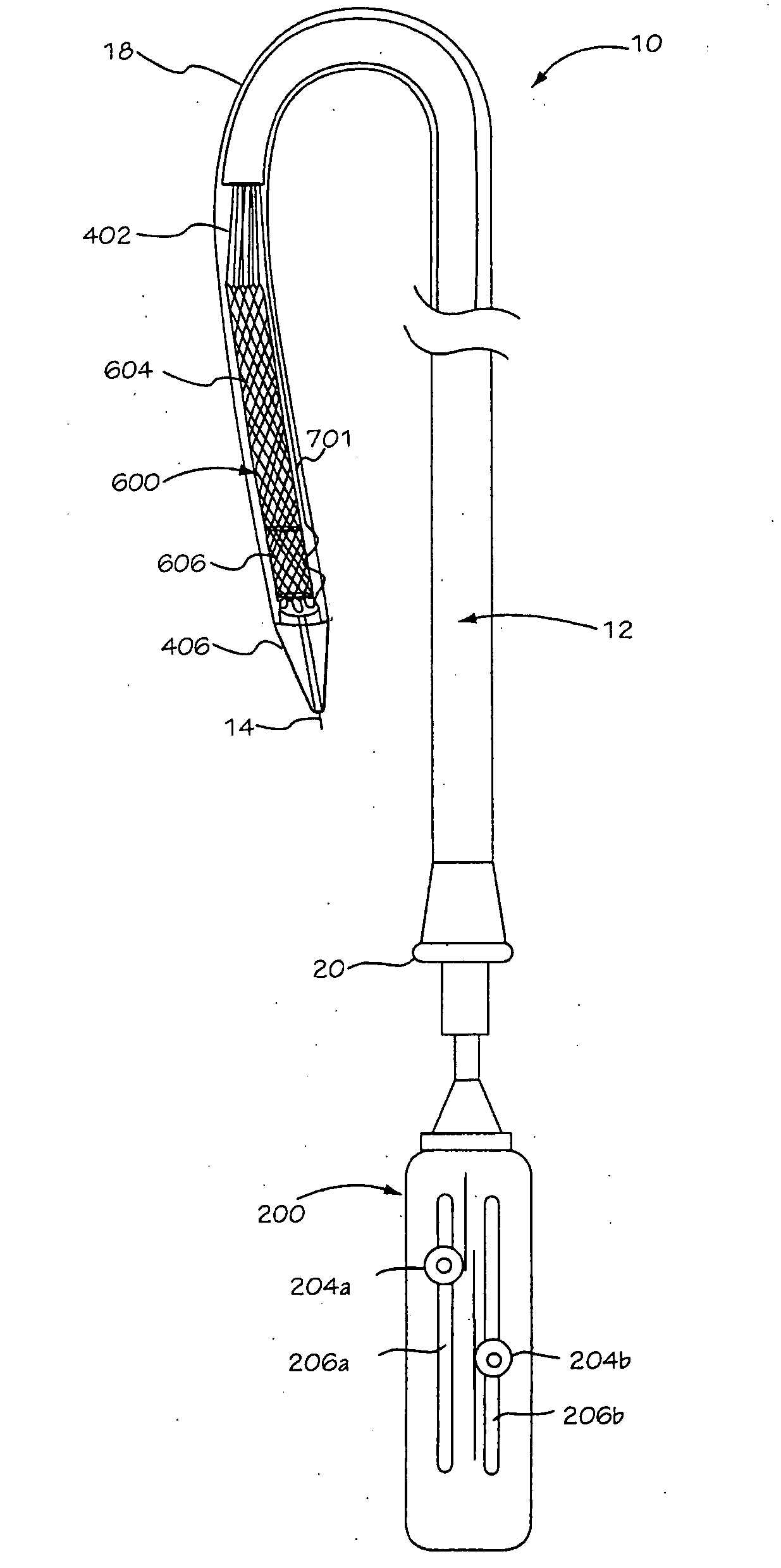
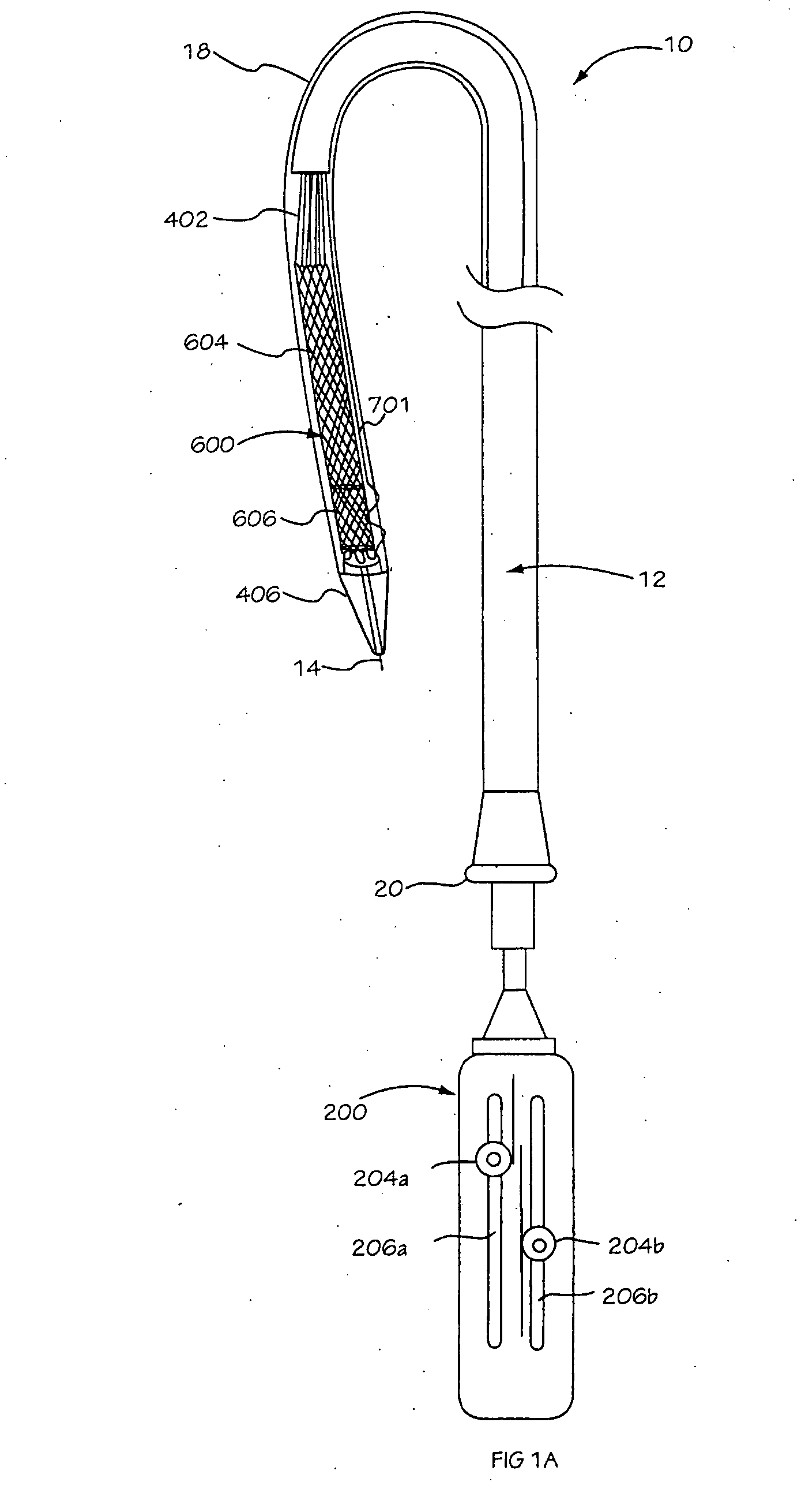
[0035]The present invention provides for a delivery sheath for use as part of an implant deployment system. In some embodiments, the deployment system is characterized by having numerous actuating elements for the mechanical operation of various movable parts used to engage and deploy an implant. A specialized sheath is desirable for use as part of the deployment system to provide the ability of deploying and sheathing the implant without harming the implant or deployment tool. Furthermore, the sheath described herein has sufficient axial stiffness to enable advancement of the sheath through the vasculature while retaining sufficient compliance to permit movement of the sheath through bends in the vasculature. In addition, the sheath incorporates a distal tip having sufficient stiffness to enable the application of a sheathing force to collapse an expandable device so that it may be drawn into the distal end of the sheath. It is desirable to minimize sheathing force in order to faci...


PUM

PropertyMeasurementUnit
forceaaaaaaaaaa
lengthaaaaaaaaaa
radial stiffnessaaaaaaaaaa

Abstract

A support member for a catheter sheath is disclosed. The support member has a series of ribs with a distal member having integrated fingers for providing radial compliance. The support member provides sufficient axial stiffness to provide a desired pushability of a minimally invasive device for replacing a heart valve. Various alternative embodiments are also described.

Description

CROSS-REFERENCE[0001]This application claims the benefit of U.S. Provisional Application No. 60 / 717,916; filed Sep. 16, 2005, which is incorporated herein by reference in its entirety.BACKGROUND OF THE INVENTION[0002]The present invention relates to sheaths for use with catheters or other endovascularly or laparoscopically delivered devices.[0003]One of the most important advances in surgery over the last few decades has been the adoption and routine performance of a variety of minimally invasive procedures. Examples of minimally invasive procedures include angioplasty, endoscopy, laparoscopy, arthroscopy and the like. Minimally invasive procedures such as these can be distinguished from conventional open surgical procedures in that access to a site of concern within a patient is achieved through a relatively small incision, into which a tubular device (such as a catheter) is inserted or introduced. The tubular device or device portion keeps the incision open while permitting access...

Claims


Application Information

Patent Timeline
Patent Type & Authority Applications(United States)
IPC IPC(8): A61F2/24
CPCA61M25/0045A61M25/0051A61M25/0053A61M25/0054A61M25/0074A61F2002/9534A61M25/0138A61M25/0662A61F2/2427A61F2/2436A61F2002/9528A61M25/008
Inventor SALAHIEH, AMRLEUNG, EMMAHILDEBRAND, DANIELLEPAK, JONAHHAUG, ULRICH R.MOREJOHN, DWIGHTSAUL, TOM
Owner BOSTON SCI SCIMED INC
Why Eureka
Try Eureka