Solar collector

a solar collector and collector body technology, applied in the field of solar collectors, can solve the problems of increasing the cost associated with the burning of fossil fuels, the economic viability of such systems is not helped by metal prices, and the system is not used extensively, so as to reduce the temperature of the roof cavity, collect more energy, and reduce the effect of destructive levels

Inactive Publication Date: 2008-08-14
SOLEXUS
View PDF43 Cites 9 Cited by
  • Summary
  • Abstract
  • Description
  • Claims
  • Application Information

AI Technical Summary

Benefits of technology

[0038]Embodiments of the solar collector may make use of surface selective coatings and insulation underneath the absorber structure while still maintaining summer time stagnant temperatures below destructive levels such that the use of inexpensive non-performance plastics is acceptable.
[0039]Where a solar collector covers a substantial part of the solar noon facing roof it may also help to lower roof cavity temperatures and hence internal house temperatures in summer by providing a good form of reflective and non-reflective insulation on the roof.
[0040]A preferred solar collector may collect more energy in winter or a relatively constant supply of heat energy in the four seasons and it may thereby avoid overheating of storage tank water and hence avoid the need for an active heat preventative provision in the summer. Such solar collectors may also provide a flatter heat collection curve throughout the day, eliminating sharp collection peaks especially in the summer months.
[0041]Although some plastics may be less robust materials, a plastic collector may still provide a longer lasting collector. Such collectors, for example, may not suffer from problems including internal corrosion or clogging with deposits from use of hard water, or damaged due to freezing of water inside inflexible metal piping, as do metal collectors. Because the top glazing cover may need periodic replacement solar collectors may have a provision for the easy replacement of this plastic cover which substantially covers the entire collector and which blocks a substantial amount of UV radiation.
[0042]Solar collectors may be sufficiently light that a slim-line roof supported collector may take advantage of a typical roof as an existing flat supporting structure and hence to obviate the need for any extensive internal or external collector supporting or stiffening structures. Such a collector might use a minimum of materials in construction resulting in a lower cost of production.

Problems solved by technology

The increasing environmental costs associated with such effects are expected to force governments around the world to eventually introduce taxes on the burning of fossil fuels or carbon trading schemes, both of which would increase the cost associated with the burning of fossil fuels.
The use of incident solar radiation for the above mentioned applications is an obvious and fitting alternative to burning fossil fuels and yet presently, such systems are not used extensively.
Glass / metal solar hot water system have found some use, but yet even these systems are mostly subsidized by government rebates due to their high up-front costs.
Needless to say the recent spike in metal prices has not help the economic viability of such systems, since they make extensive use of copper and aluminum.
There have been numerous efforts to use plastic in the production of solar collectors due to lower material costs, yet for a variety of reasons plastic collectors have not been widely commercially produced or are not commercially competitive with glass / metal.
These are mainly due to well known limitations of plastic when used for glazing and especially absorbers.
The main limitation concerns the exposure of absorber components, or other structural components of the collector to extreme temperatures under stagnant conditions, where the collector is exposed to full sun conditions and where the internal cooling fluid does not flow.
Panel exposure to stagnant conditions is common and can take place during installation or pump, controller or value failure and can easily cause catastrophic damage to plastic collectors or severely limit the collector's life time.
This can mandate the use of performance plastics for absorbers and associated components which can withstand these high temperatures but unfortunately such performance plastics are much more costly.
The simplest of these allow significant heat loss from the top face of the panel through the use of non-selective coatings for the absorber and glazing or the outright lack of a glazing cover as in pool type solar collector, or the lack of underside insulation.
Unfortunately, all of these limit the efficiencies of such solar panels and hence limit their use specifically in winter.
More sophisticated passive methods include the use of materials which change their transmission of light as a function of temperature, but these have not found use as solar collector components.
Such strategies have the obvious disadvantage of using complex moving parts and associated monitoring and controller systems which are prone to high maintenance costs and eventual failure.

Method used


Image

  • Solar collector
  • Solar collector
  • Solar collector

Examples


Embodiment Construction

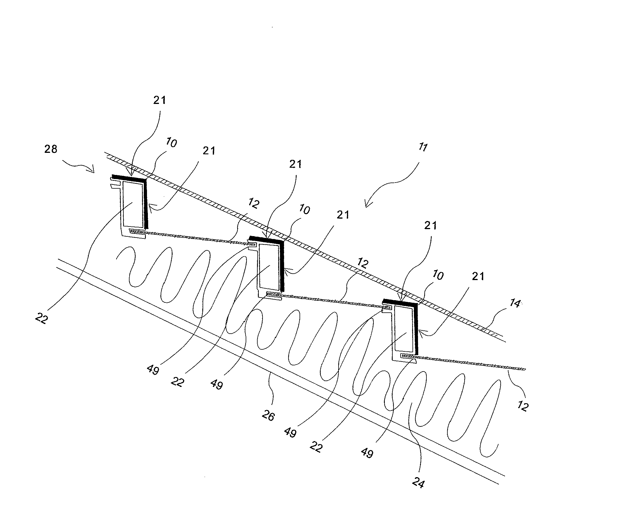
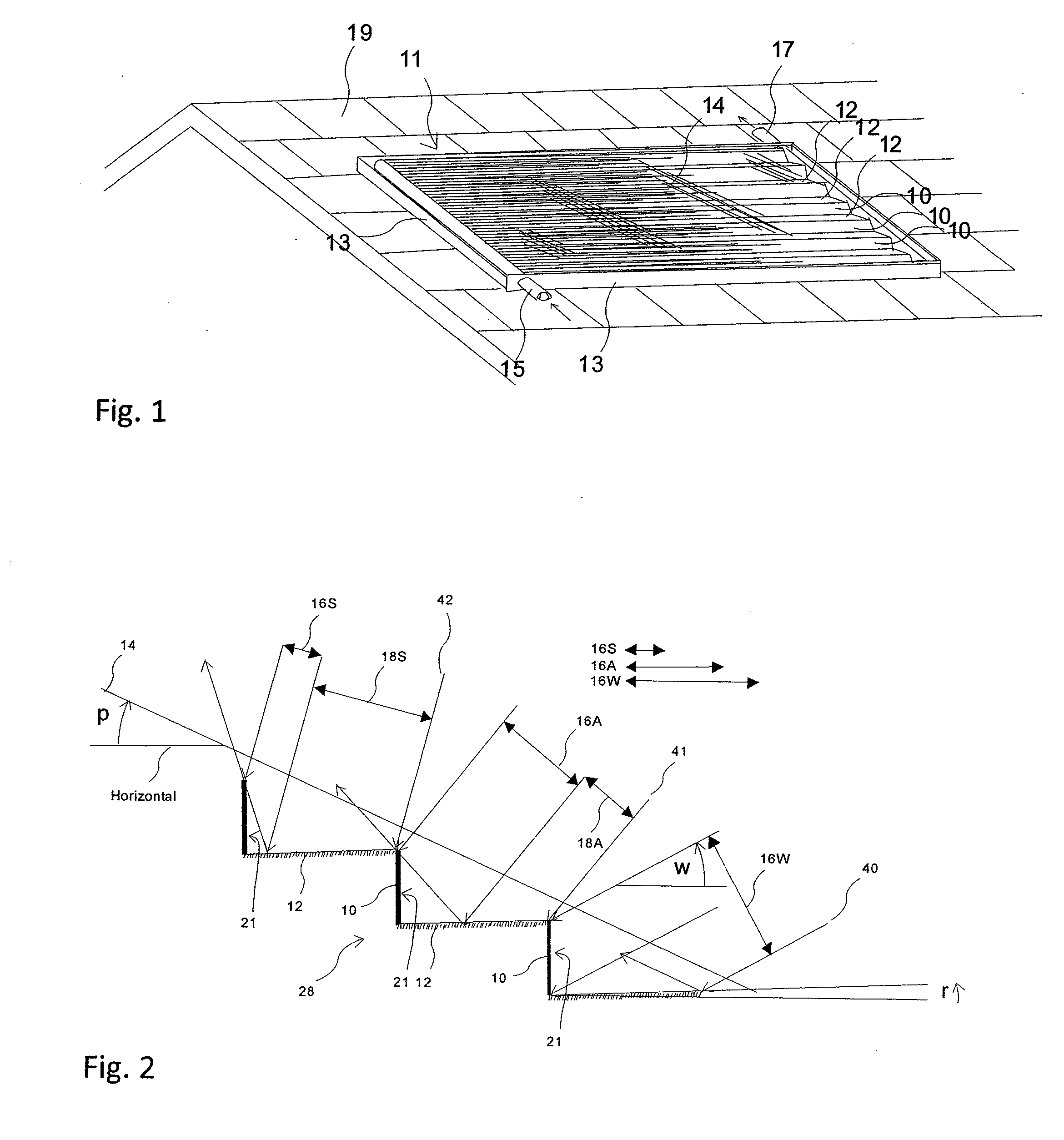
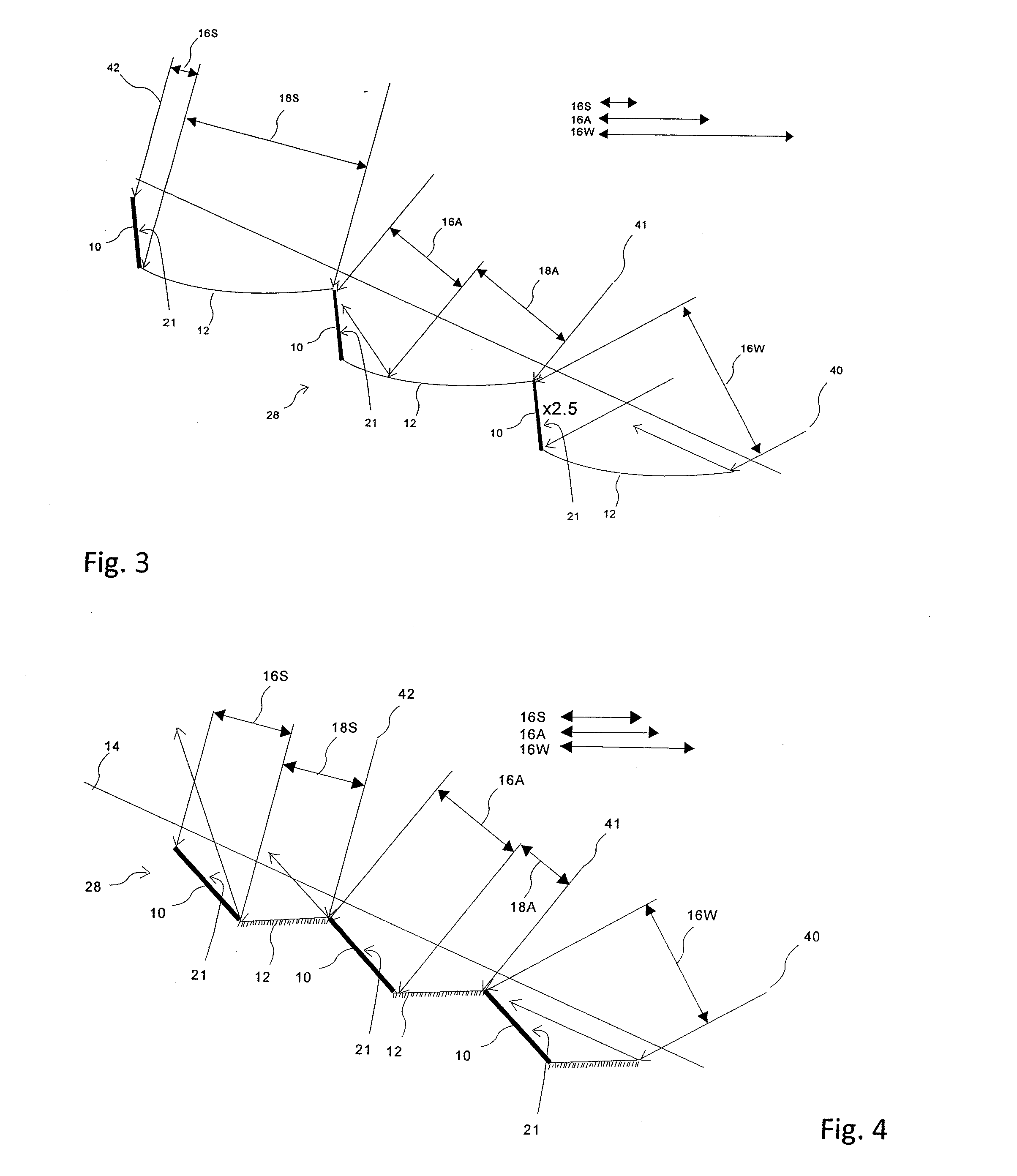
[0060]Referring to FIG. 1 a solar collector 11 is shown fitted to a roof structure 19. Such an installation may be made as a retrofit or may be completed at the time of building in which case the roof may be modified specifically to allow simplified installation and ducting of pipe work. The embodiment shows a solar collector 11 with a typical casing structure including side walls 13, top cover 14, and a bottom cover or wall 26 (ref FIGS. 6-14&16), with an internal arrangement of absorber elements 10 and reflectors 12 configured in a step-like structure. Inlet 15 and outlet 17 end piping connections are provided for the absorber fluid channels 22 (ref FIGS. 6-15). Piping (not shown) connected to the inlet 15 and outlet 17 will be lead from the roof 19 and connected to a heat storage system or used directly for the provision of useful heat.

[0061]The preferred solar collector 11 is a low profile panel which absorbs solar energy and converts it to heat. A passive or non-mechanical meth...


PUM


Abstract

A low profile solar collector collects solar energy as heat, while limiting possible peak stagnant temperatures in the collector in summer months.
The collector has a plurality of reflectors, each having longitudinal edges parallel to an adjacent reflector such that the reflective elements are arranged in a fixed offset parallel array, which forms a staircase of upwardly facing reflective surfaces in use.
Absorber elements are located between adjacent pairs of reflectors. The absorber elements each have an exposed surface located between each pair of reflective elements, and arranged to extend between a first edge of one reflector and a second edge of an adjacent reflector. The exposed surfaces of the absorber elements are disposed at an angle to each of the reflective elements to thereby form a fixed parallel array of exposed surfaces of the absorber elements.
A transparent top cover extends over the reflective and absorber elements.
In use the reflective elements are oriented in a first generally horizontal orientation such that incident sunlight passing through the top cover either falls directly onto the exposed surface of each absorber element or the incident sunlight falls a reflector adjacent to an exposed surface of one of the absorber elements and reflects onto the respective exposed surface.

Description

CROSS-REFERENCE TO RELATED APPLICATIONS[0001]The present application claims priority from Australian Provisional Patent Application No 2007900662 filed on 12 Feb. 2007, and Australian Provisional Patent Application No 2007901492 filed on 21 Mar. 2007, the contents of which are incorporated herein by reference.[0002]The present invention relates to the use of solar collectors to collect energy in the form of heat from solar radiation for uses such as space heating and hot water supply for residential, commercial or industrial buildings.[0003]Presently, there is growing concern about the global warming effects caused by the burning of fossil fuels, such as for example in fueling space heaters and domestic hot water systems. The increasing environmental costs associated with such effects are expected to force governments around the world to eventually introduce taxes on the burning of fossil fuels or carbon trading schemes, both of which would increase the cost associated with the burn...

Claims


Application Information

Patent Timeline
Patent Type & Authority Applications(United States)
IPC IPC(8): F24J2/10F24J2/50F24S23/70F24S23/77F24S23/79
CPCF24J2/0488F24J2/16F24J2/202F24J2/4621Y02E10/44F24J2/51F24J2002/1014F24J2002/503Y02B10/20F24J2/50F24S2023/832F24S80/60F24S70/60F24S40/50F24S2080/503F24S10/502F24S23/77F24S80/56F24S80/58
Inventor GROCHOLA, GREGORY MARTIN
Owner SOLEXUS
Why Eureka
Try Eureka