Additive dispersing filter and method of making

a technology of additive dispersing filter and additive dispersing, which is applied in the direction of liquid displacement, lubricant mounting/connection, separation process, etc., can solve the problems of increased engine wear, depletion, and contamination formation, and achieve the effect of prolonging the useful life of engine oil and prolonging the time interval

Active Publication Date: 2008-08-14
BMO HARRIS BANK N A AS SUCCESSOR COLLATERAL AGENT +1
View PDF6 Cites 11 Cited by
  • Summary
  • Abstract
  • Description
  • Claims
  • Application Information

AI Technical Summary

Benefits of technology

[0011]Therefore it is desirable to provide a filter having an additive incorporated therein, wherein the additive is slowly released over the useful life of the filter. I...

Problems solved by technology

In the oil filtration art, it is well known that normal operation of an internal combustion engine, particularly a diesel engine, results in the formation of contaminants.
These contaminants are typically introduced into the lubricating oil during engine operation, and tend to increase oil viscosity and generate unwanted engine deposits, leading to increased engine wear.
These work well for a short period, but may become depleted.
Additionally, due to the solubility and chemical stability limits of these dispersants in the oil, the service lives of the lubricating oil and the oil filter are less than optimal.
The depletion of the TBN is an important limiting factor for many internal combustion engines, particula...

Method used


Image

  • Additive dispersing filter and method of making
  • Additive dispersing filter and method of making
  • Additive dispersing filter and method of making

Examples


example filter

Design

[0054]Average flow rate through single filter at average speed of 60 mph-13.25 gpm.

[0055]Calculated average fluid velocity flowing past stagnation tube—2.22 ft / sec.

[0056]The fluid velocity can be calculated by knowing the area between the additive cartridge housing and the inner surface of the filter housing it is secured in, the flow rate of the fluid or oil passing through the filter can then be used to calculate the velocity of the fluid using known principles or formulas to calculate the velocity of the fluid passing through the filter.

[0057]A non-limiting example is produced below:

Stagnation Pressure CalculationsPressure = ½ * mass density * V{circumflex over ( )}2weight density of oil (lbs. / cu. Ft)56.02Mass density of oil − weight density / 1.739751553g (lb sec{circumflex over ( )}2 / ft{circumflex over ( )}4)specific gravity of oil0.898Pressure (lbs / ft{circumflex over ( )}2)4.274813125Stagnation Pressure (lbs / in{circumflex over ( )}2)0.0296862021.44 inch / H2O

[0058]In one exe...


PUM

PropertyMeasurementUnit
Forceaaaaaaaaaa
Pressureaaaaaaaaaa
Flow rateaaaaaaaaaa

Abstract

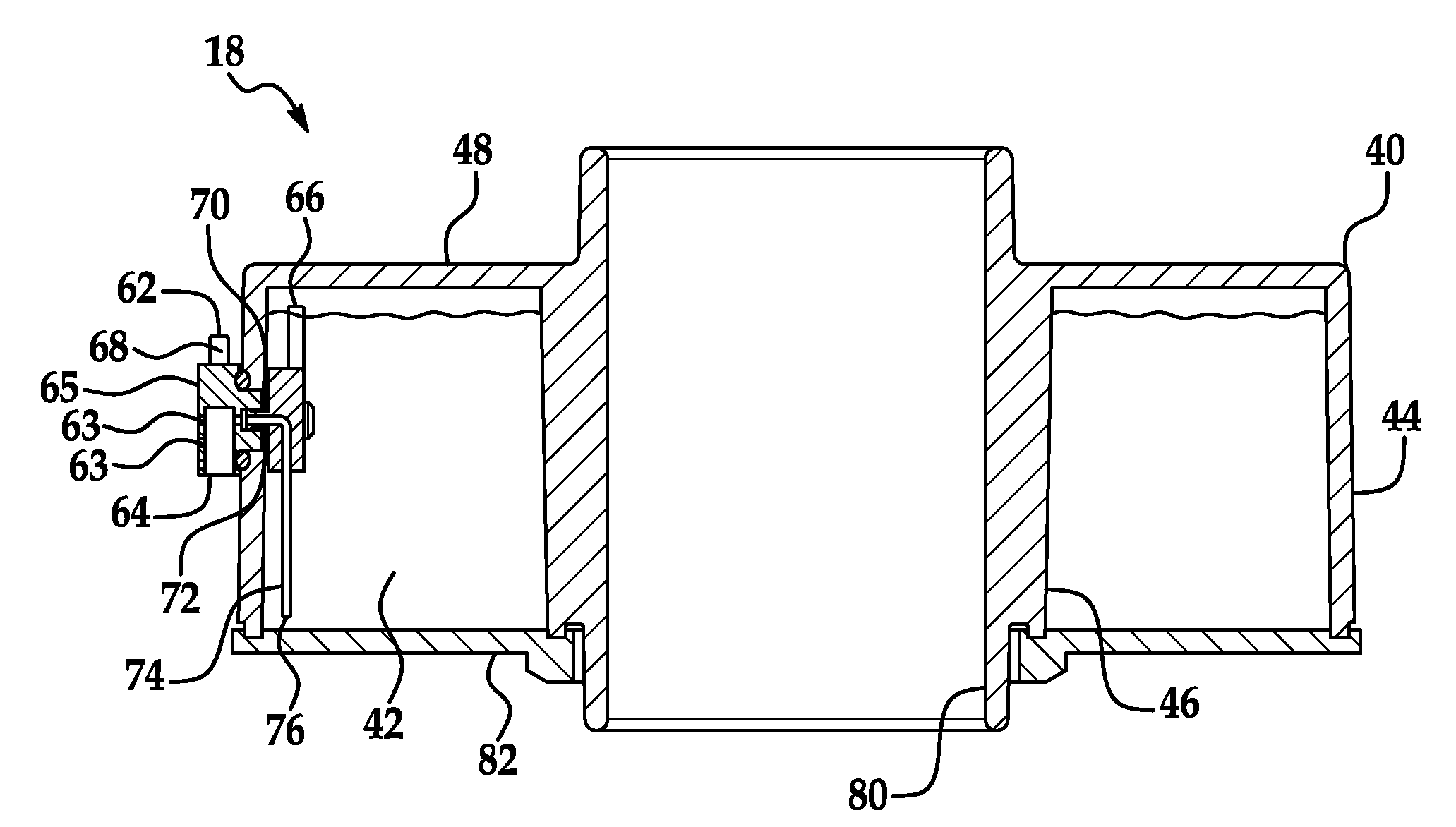
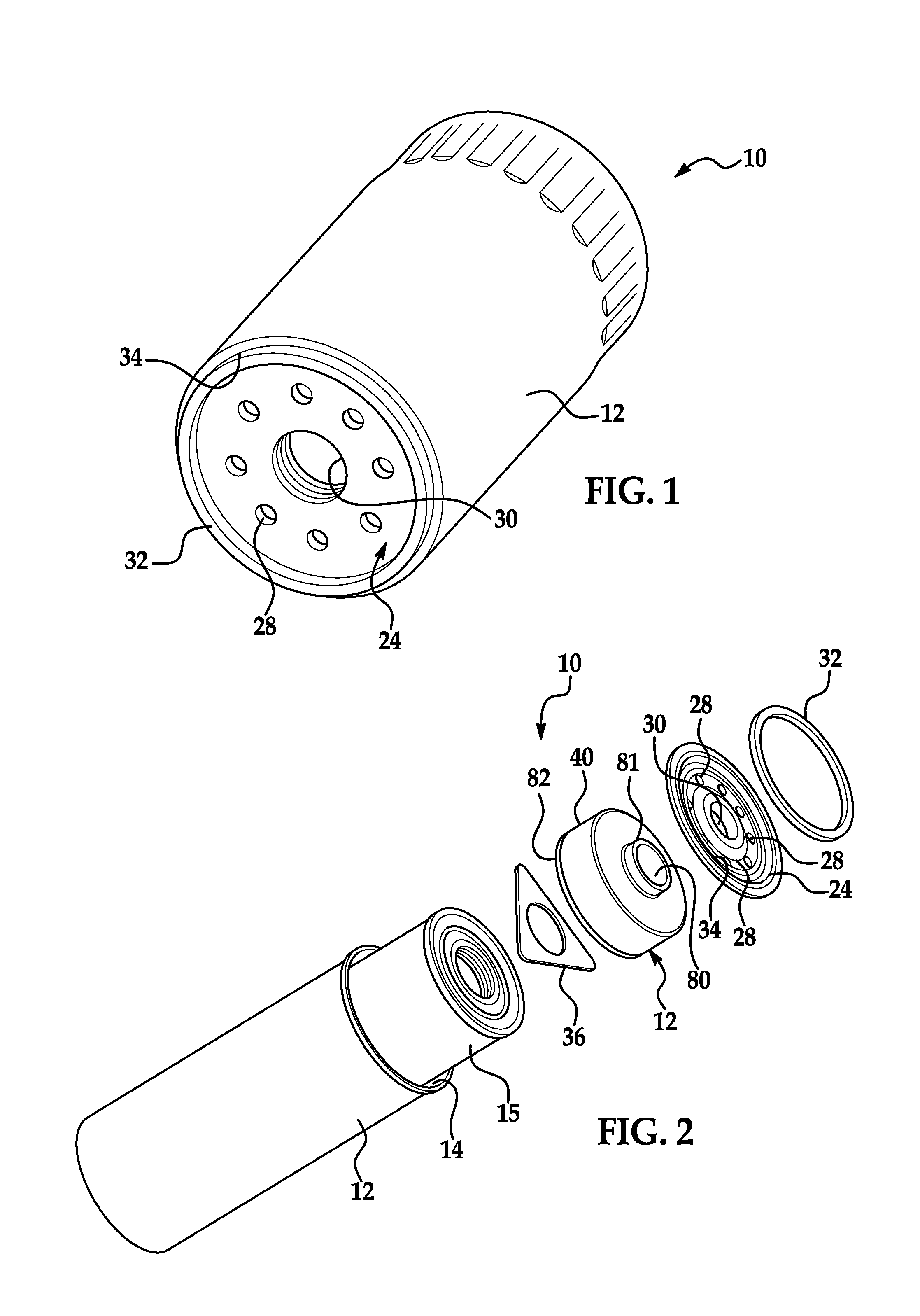
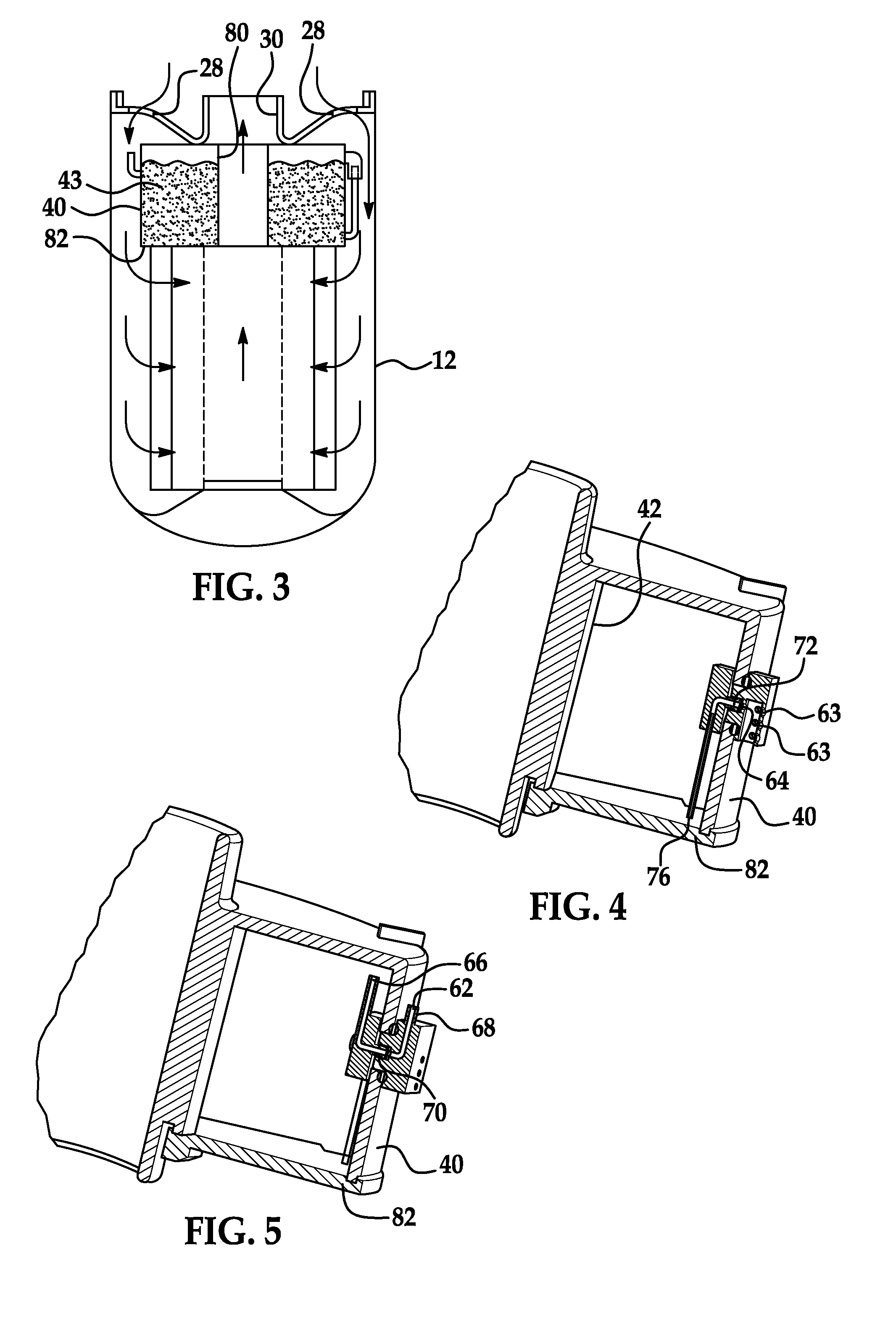
A method for dispersing an additive from an additive cartridge disposed in a housing of an oil filter is provided herein, the method includes using stagnation pressure to disperse the additive from the additive cartridge; and regulating a flow rate of the additive from the additive cartridge by restricting an inlet opening of an outlet tube of the additive cartridge. Also provide herein is an additive cartridge for dispersing an additive within a filter housing, the additive cartridge having a housing defining a receiving area for receipt of the additive; a fluid inlet path through a wall of the housing, the fluid inlet path providing a means for increasing a pressure within the receiving area, the fluid inlet path having an inlet opening disposed adjacent to an outer wall portion of the housing; and a fluid outlet path through the wall of the housing, the fluid outlet path providing a means for dispersing the additive from the receiving area when the pressure within the receiving area exceeds a predetermined value, the fluid outlet path having an outlet opening disposed adjacent to the outer wall portion of the housing, the outlet opening being covered by a shroud configured to deflect fluid flowing in a first direction away from the outlet opening and the inlet opening of the fluid inlet path is positioned to receive fluid flowing in the first direction; and fluid flow of the additive through the fluid outlet path is controlled by varying an inlet opening of the fluid outlet path.

Description

CROSS REFERENCE TO RELATED APPLICATIONS[0001]The present application claims the benefit of the following provisional patent applications Ser. No. 60 / 889,728, filed Feb. 13, 2007; Ser. No. 60 / 910,772 filed Apr. 9, 2007; and Ser. No. 60 / 985,193 filed Nov. 2, 2007 the contents each of which are incorporated herein by reference thereto.BACKGROUND[0002]Exemplary embodiments of the present invention relate to an additive dispersing filter and method of dispersing an additive to a fluid passing through the filter.[0003]Many different types of fluid filters are known. Most such filters use a mechanical or ‘screening’ type of filtration, with a porous filter element disposed therein. The oil is repeatedly cycled through the filter element to remove impurities.[0004]In the oil filtration art, it is well known that normal operation of an internal combustion engine, particularly a diesel engine, results in the formation of contaminants. These contaminants include, among others, soot, which is f...

Claims


Application Information

Patent Timeline
IPC IPC(8): B01F3/00B01F23/00
CPCB01D37/025B01F1/0033F01M2001/1014F01M11/03F01M9/02Y10T137/87587B01F21/221
Inventor BILSKI, GERARD W.HUSSAIN, ZAFAR
Owner BMO HARRIS BANK N A AS SUCCESSOR COLLATERAL AGENT
Why Eureka
Try Eureka