
Illumination System Comprising a Ceramic Luminescence Converter

a luminescence converter and ceramic technology, applied in the direction of solid-state devices, discharge tube/lamp details, inorganic chemistry, etc., can solve the problems of difficult to produce uniform emission characteristics from batch to batch, low yield of conventional visible colored light emitting leds, etc., to achieve the effect of long-lasting and durabl

Inactive Publication Date: 2008-08-14
KONINKLIJKE PHILIPS ELECTRONICS NV
View PDF8 Cites 20 Cited by
  • Summary
  • Abstract
  • Description
  • Claims
  • Application Information

AI Technical Summary

Benefits of technology

[0017]It is therefore an object of the present invention to provide an illumination system for generating of white light, which has true color rendition and is durable and long-living.

Problems solved by technology

Conventional visible colored light emitting LEDs, however, are typically subject to low yield and are considered difficult to fabricate with uniform emission characteristics from batch to batch.
Therefore, when generating white light with an arrangement comprising visible colored light emitting diodes, there has been such a problem that white light of the desired tone cannot be generated due to variations in the tone, luminance and other factors of the visible colored light emitting diodes.
As recent advances in light-emitting diode technology have yielded very efficient light-emitting diodes emitting on the near UV to blue range of the electromagnetic spectrum, today a variety of colored and white-emitting phosphor converted light emitting diodes are on the market, challenging traditional incandescent or fluorescent lighting.
Designing luminescent material for use in such devices is a new challenge, as there are few luminescent materials with an absorption spectrum in the near UV / blue range of the electromagnetic spectrum available, that can efficiently convert said near-UV / blue radiation to visible colored or white light, while maintaining long-term stability.
Yet, in prior art it was annotated, that sulfide-based phosphors such as earth alkaline sulfides are less desirable for lighting applications, especially for LED applications, because they interact with the encapsulating resin system, and particularly suffer from hydrolytic attack, see U.S. Pat. No. 6,682,663 B2.

Method used


Image

  • Illumination System Comprising a Ceramic Luminescence Converter
  • Illumination System Comprising a Ceramic Luminescence Converter
  • Illumination System Comprising a Ceramic Luminescence Converter

Examples


first embodiment

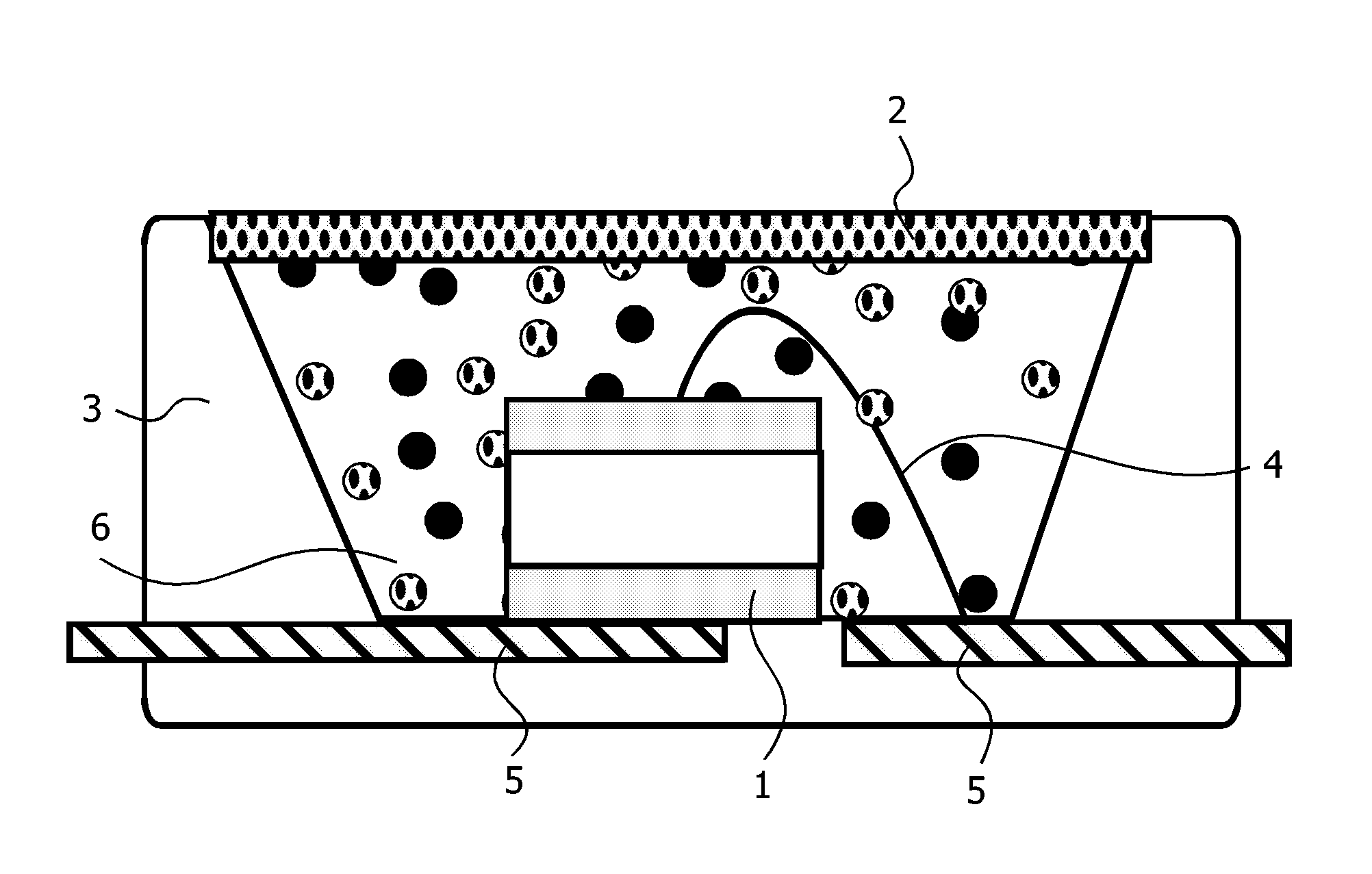
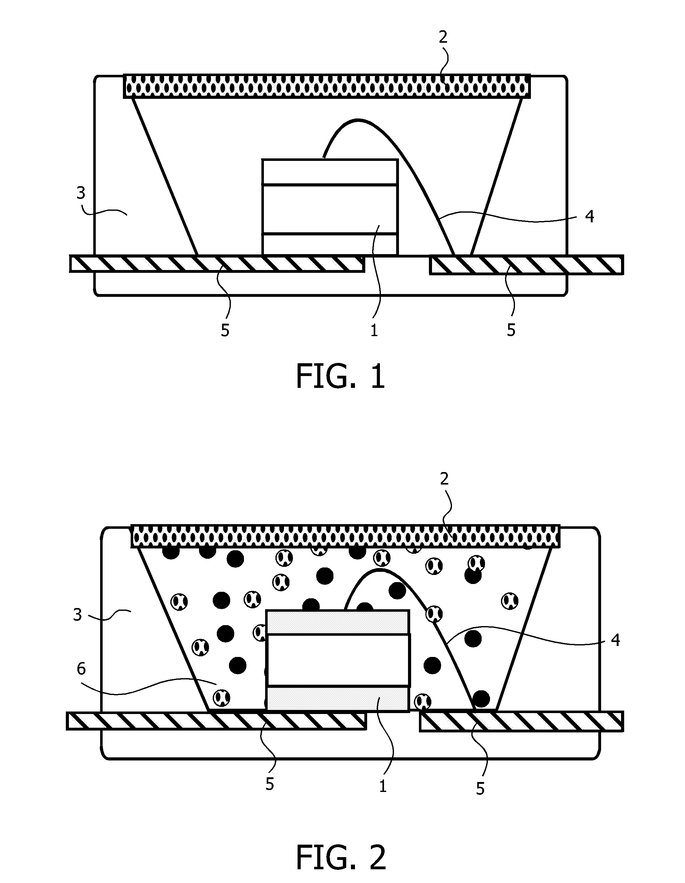
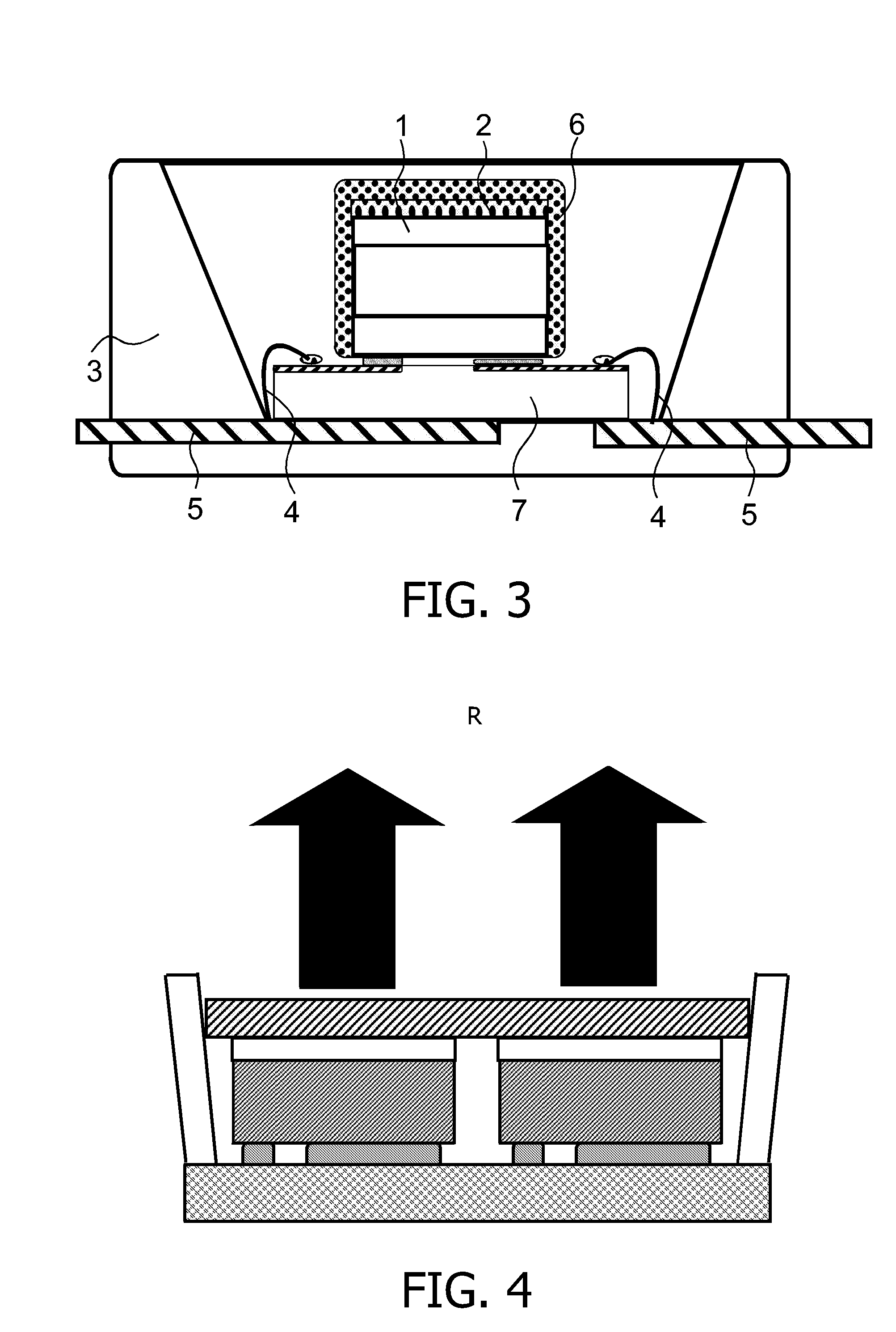
[0099]In a white-light emitting illumination system according to the invention the device can advantageously be produced by choosing the luminescent material of the monolithic ceramic luminescence converter such that a blue radiation emitted by a blue light emitting diode is converted into complementary wavelength ranges in the amber range, to form dichromatic white light, as shown in FIG. 10.

[0100]Particularly good results are achieved with a blue-emitting LED whose emission maximum lies at 420 to 480 nm. An optimum has been found to lie at 455 nm, taking particular account of the excitation spectrum of the activated earth alkaline sulfides according to the invention.

[0101]Amber light is produced by means of the phosphor material of the monolithic ceramic luminescence converter, that comprises an alkaline earth metal sulfide of general formula AE1-zS1-ySey:Az, wherein AE is as least one earth alkaline metal selected from the group of Mg, Ca, Sr and Ba, 0≦y<1 and 0.0005≦z≦0.2, activ...

second embodiment

[0104]In a second embodiment yielding white light emission with even higher color rendering is provided by using a blue-emitting LED, an amber and red emitting monolithic ceramic luminescence converter comprising an activated earth alkaline sulfide together with a second luminescence converter, preferably a green broad band emitter

[0105]Such second luminescence converter may be either provided as a phosphor pigment admixed in a resin bonded encapsulation layer or as a second monolithic ceramic luminescence converter as shown in FIG. 11.

[0106]Useful second luminescence converters and their optical properties are summarized in the following table 2.

TABLE 2Compositionλmax [nm]Color point x, y(Ba1−xSrx)2SiO4:Eu5230.272, 0.640SrGa2S4:Eu5350.270, 0.686SrSi2N2O2:Eu5410.356, 0.606SrS:Eu6100.627, 0.372(Sr1−x−yCaxBay)2Si5N8:Eu6150.615, 0.384(Sr1−x−yCaxBay)2Si5−aAlaN8−aOa:Eu615-650*CaS:Eu6550.700, 0.303(Sr1−xCax)S:Eu610-655**color point depending on the value of x

[0107]For improved color rendi...


PUM

PropertyMeasurementUnit
wavelengthsaaaaaaaaaa
temperatureaaaaaaaaaa

Abstract

An illumination system, comprising a radiation source and a monolithic ceramic luminescence converter comprising at least one phosphor capable of absorbing a part of light emitted by the radiation source and emitting light of wavelength different from that of the absorbed light; wherein said at least one phosphor is an alkaline earth metal sulfide of general formula AE1-zS1-ySey:Az, wherein AE is at least one earth alkaline metal selected from the group of Mg, Ca, Sr and Ba, 0≦y<1 and 0.0005≦z≦0.2, activated by an activator A selected from the group of Eu(II), Ce(III), Mn(II) and Pr(III). is highly efficient, especially if a blue light emitting diode is used as a radiation source, and provides excellent thermal and spectroscopic properties. The invention is also concerned with a monolithic ceramic luminescence converter comprising at least one phosphor capable of absorbing a part of light emitted by the radiation source and emitting light of wavelength different from that of the absorbed light; wherein said at least one phosphor is an alkaline earth metal sulfide of general formula AE1-zS1-ySey:Az, wherein AE is as least one earth alkaline metal selected from the group of Mg, Ca, Sr and Ba, 0≦y<1 and 0.0005≦z≦0.2, activate by an activator A selected from the group of Eu(II), Ce(II), Mn(II) and Pr(III).

Description

BACKGROUND OF THE INVENTION[0001]The present invention generally relates to an illumination system comprising a radiation source and a ceramic luminescence converter. The invention also relates to a ceramic luminescence converter for use in such illumination system.[0002]More particularly, the invention relates to an illumination system and a ceramic luminescence converter for the generation of specific, colored light, including white light, by luminescent down conversion and additive color mixing based an a ultraviolet or blue radiation emitting radiation source. A light-emitting diode as a radiation source is especially contemplated.[0003]Today light emitting illumination systems comprising visible colored light emitting diodes as radiation sources are used single or in clusters for all kind of applications where rugged, compact, lightweight, high efficiency, long-life, low voltage sources of white or colored illumination are needed.[0004]Such applications comprise inter alia illu...

Claims


Application Information

Patent Timeline
Patent Type & Authority Applications(United States)
IPC IPC(8): H01J1/63C01F17/00C01B19/00H01L33/50
CPCC09K11/0883C09K11/7718C09K11/7731C09K11/7734H01L33/502H01L2224/73265C04B35/547C04B2235/3208C04B2235/3213C04B2235/3224H01L2224/48247H05B33/14H01L2224/73253H01L2924/16195C09K11/77347C09K11/77342C09K11/77348
Inventor SCHMIDT, PETER J.
Owner KONINKLIJKE PHILIPS ELECTRONICS NV
Learn More