
Flat panel display having a backlight module

Inactive Publication Date: 2008-08-14
INNOLUX CORP
View PDF9 Cites 3 Cited by
  • Summary
  • Abstract
  • Description
  • Claims
  • Application Information

AI Technical Summary

Benefits of technology

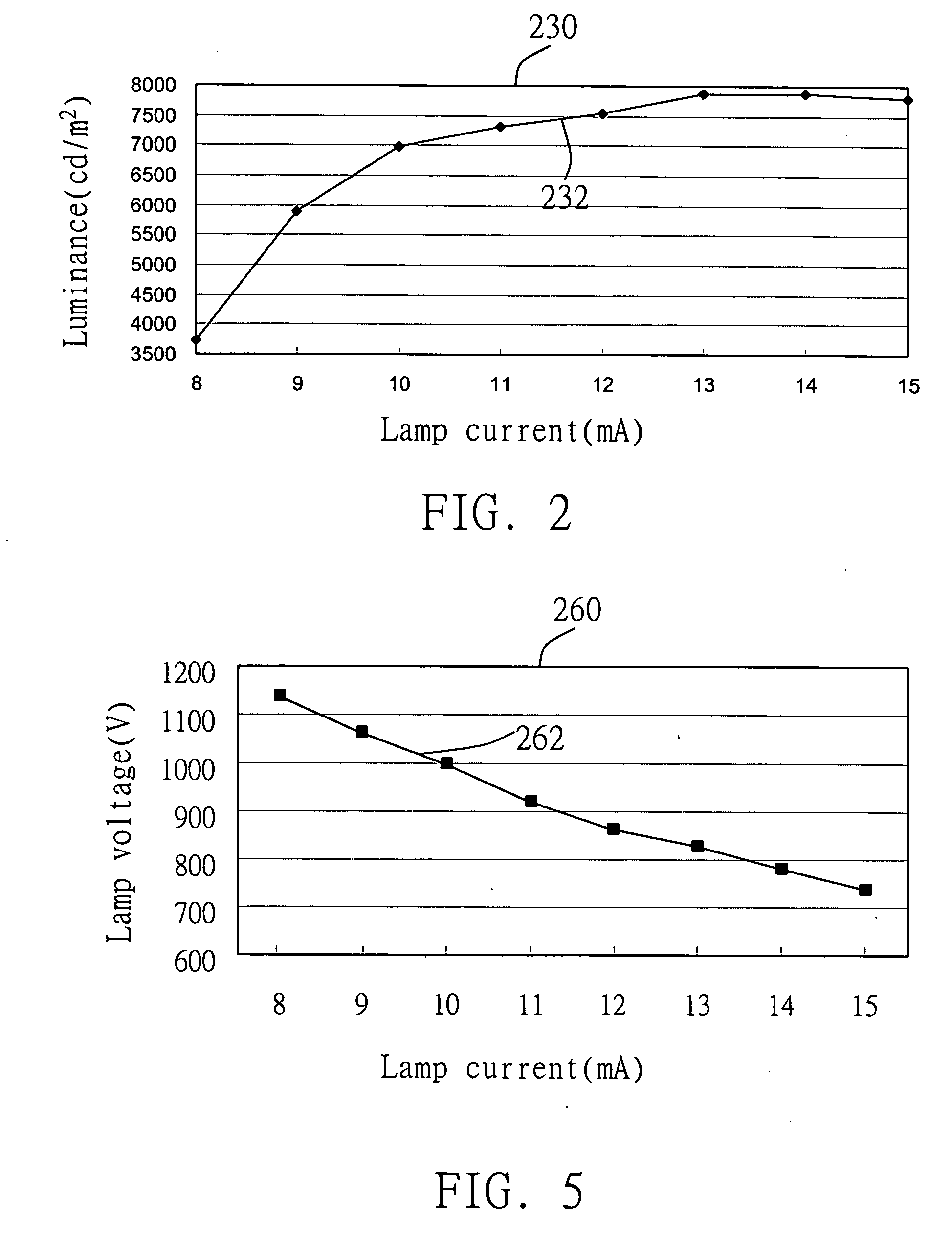
[0018]Advantages of the apparatuses and methods may include one or more of the following. By driving the lamp using a higher current closer to the saturation current, the voltage for driving the lamp can be reduced, the leakage current can be reduced, the luminance uniformity of the lamp from one end to the other end can be increased, and the overall luminance uniformity of the display can be enhanced. This is particularly useful for large size displays in which the lengths of the lamps are long. Also, by reducing leakage current, operating the backlight module requires less energy. For mobile devices that use battery to power the backlight module, this results in longer battery life. By driving the lamp using a lamp current close to the saturation current level so that the lamp outputs are near saturation luminance, differences in the luminance of different lamps can be reduced, increasing uniformity of luminance across the display. By operating the lamps so that luminance is more uniform throughout the lengths of the lamps, a single side driving scheme can be used instead of a double side driving scheme, reducing the cost of the display.

Problems solved by technology

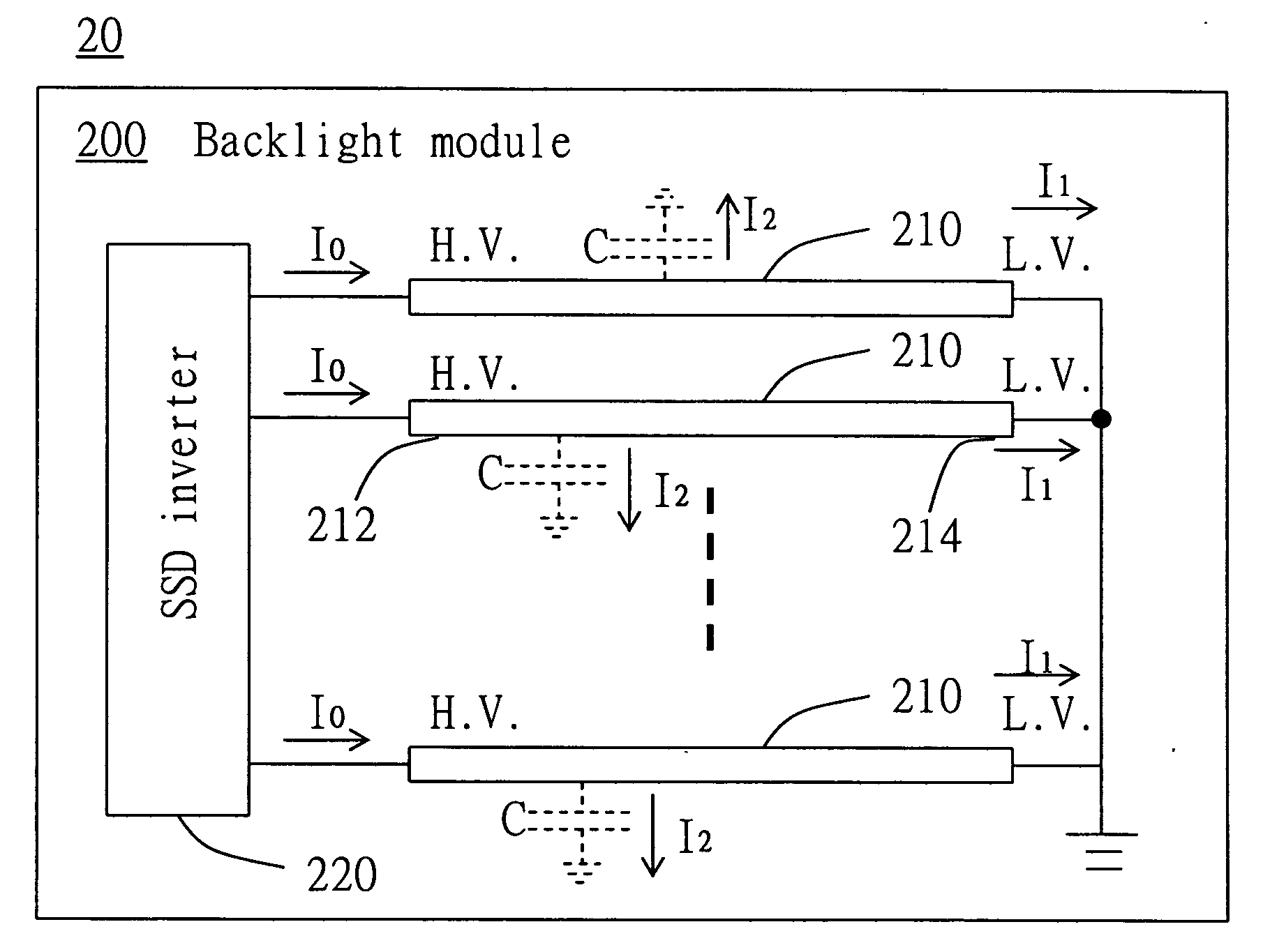
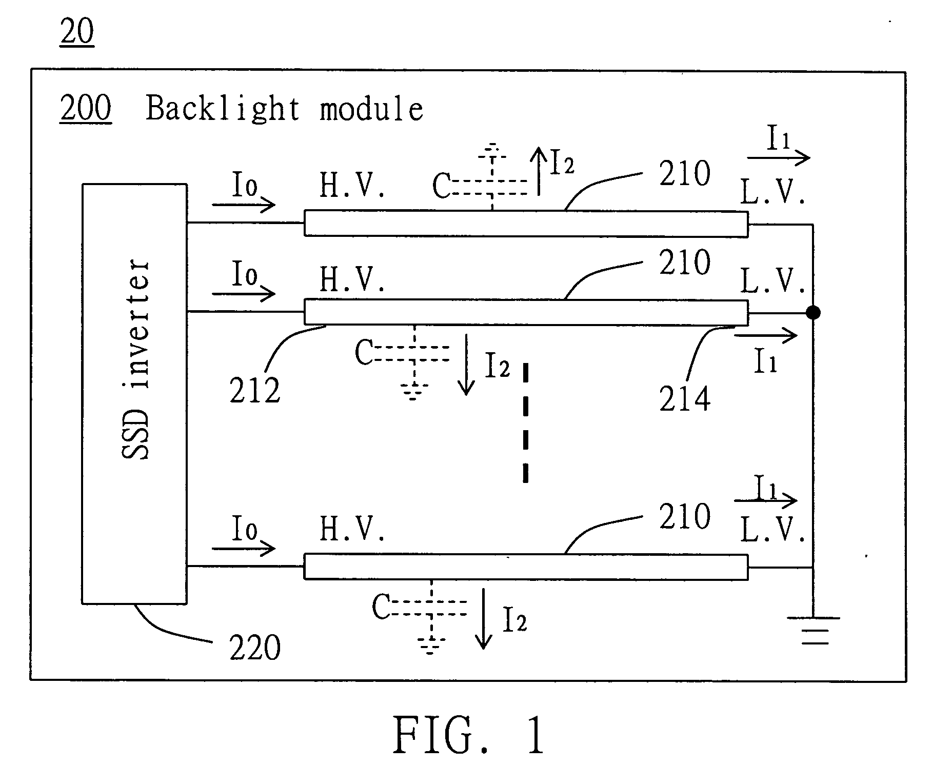
Due to the large voltage difference between the two ends of the lamps, leakage current may flow through the parasitic capacitors to system ground.
For lamps that are used in large size flat panel displays (e.g., having a diagonal size of 37 inches and above), the leakage current may be sufficiently large to causes the luminance to vary from one end of the lamp to the other end, causing non-uniformity in display luminance.
For mobile devices that use battery to power the backlight module, this results in longer battery life.

Method used


Image

  • Flat panel display having a backlight module
  • Flat panel display having a backlight module
  • Flat panel display having a backlight module

Examples


Embodiment Construction

[0027]Referring to FIG. 1, a flat panel display 20 can have a more uniform luminance by operating lamps 210 of a backlight module 200 near saturation, as compared to operating the lamps 210 with lower currents. Due to a negative resistance property of the lamps, operating the lamps 210 near saturation allows the operating voltage of the lamps 210 to be reduced, also reducing leakage current, so that luminance of the lamps 210 is more consistent throughout the entire lengths of the lamps 210. By reducing leakage current, power consumption can be reduced, increasing battery life for portable devices.

[0028]The flat panel display 20 can be, e.g., a liquid crystal display. The lamps 210 can be, e.g., CCFLs. Each lamp 210 has a high voltage end 212 and a low voltage end 214. The display 20 includes a single side driving (SSD) inverter 220 that converts a DC voltage to an AC voltage (e.g., 100 to 1200V rms). The SSD inverter 220 applies the AC voltage to the high voltage end 212 of each la...


PUM


Abstract

A backlight module that includes a lamp and a single side driving inverter that is coupled to one end of the lamp. The single side driving inverter is configured to control an operating current of the lamp to be within 80% to 100% of a saturation luminance current. The lamp has a characteristic such that when the operating current is lower than the saturation luminance current, the lamp luminance increases as the operating current increases, and when the operating current is substantially equal to or higher than the saturation luminance current, the lamp luminance does not increase as the operating current increases.

Description

CROSS-REFERENCE TO RELATED APPLICATIONS [0001]This application claims priority to Taiwan application serial no. 94140161, filed Nov. 15, 2005, the contents of which are incorporated by reference.BACKGROUND OF THE INVENTION [0002]The description relates to flat panel displays that have backlight modules.[0003]An example of a flat panel display is a liquid crystal display. In a transmissive or transflective type liquid crystal display, a backlight module generates light that is modulated by a liquid crystal layer to form an image. The backlight module can include lamps, e.g., cold cathode fluorescent lamps (CCFLs), and drivers for driving the lamps using single-side driving or double-side driving. When single-side driving is used, a single-side-driving inverter converts a DC voltage to an AC voltage having a high root-mean-square (rms) value (e.g., over 100V) and a high frequency (e.g., over 1000 Hz) that is applied to one end of each lamp, with the other end of the lamp connected to ...

Claims


Application Information

Patent Timeline
IPC IPC(8): H05B41/16H04N3/14
CPCH05B41/2822
Inventor CHEN, SHIH-MINGLEE, YONG-LONG
Owner INNOLUX CORP
Learn More