Laser Microscope

a laser microscope and microscope technology, applied in the field of laser microscopes, can solve the problems of impaired multiphoton excitation efficiency, increased pulse width of ultrashort-pulsed laser light emitted from the end of the objective lens, and possible use, so as to reduce the drop in output power, reduce the size of the positive dispersion element, and improve the multiphoton excitation efficiency

Inactive Publication Date: 2008-08-14
OLYMPUS CORP
View PDF7 Cites 13 Cited by
  • Summary
  • Abstract
  • Description
  • Claims
  • Application Information

AI Technical Summary

Benefits of technology

[0040]With this configuration, it is possible to adjust the average output power of the laser light source by operating the average-output-power adjusting optical system, which allows the specimen to be irradiated with the ultrashort-pulsed laser light without causing damage to the specimen.
[0041]According to the present invention, it is possible to reduce the drop in output power in a positive-dispersion element used as a pulse compressor, and the multiphoton-excitation efficiency can thus be improved. In addition, with the present invention, reducing the size of the positive-dispersion element makes it easier to attach it to the microscope main body and to accommodate it therein, thus improving maneuverability.

Problems solved by technology

When ultrashort-pulsed laser light having a femtosecond-order pulse width is introduced into the optical fiber, the high optical density inside the fiber brings about a nonlinear effect (self-phase modulation: spectral broadening) which, in conjunction with the group velocity dispersion, causes the pulse width of the ultrashort-pulsed laser light emitted from the end of the objective lens to increase, resulting in the problem of impaired multiphoton-excitation efficiency.
In the laser microscopes disclosed in Japanese Unexamined Patent Application, Publication No. 2000-206415 and U.S. Pat. No. 6,269,206, to prevent the pulse width of the ultrashort-pulsed laser light from expanding while propagating through the optical fiber, it is not possible to use a multimode fiber; instead, it is necessary to use a single-mode fiber.
However, when the amount of positive dispersion to be applied is too large, the thickness of the positive-dispersion element increases, and a drop in the output power due to internal absorption in the positive-dispersion element becomes more pronounced, which causes a reduction in the efficiency of the multiphoton-excitation effect in the specimen.
Moreover, when the amount of positive dispersion to be applied is too large, the size of the positive-dispersion element becomes large, thus making it difficult to attach it to the microscope main body and to accommodate it therein.

Method used


Image

  • Laser Microscope
  • Laser Microscope
  • Laser Microscope

Examples


Embodiment Construction

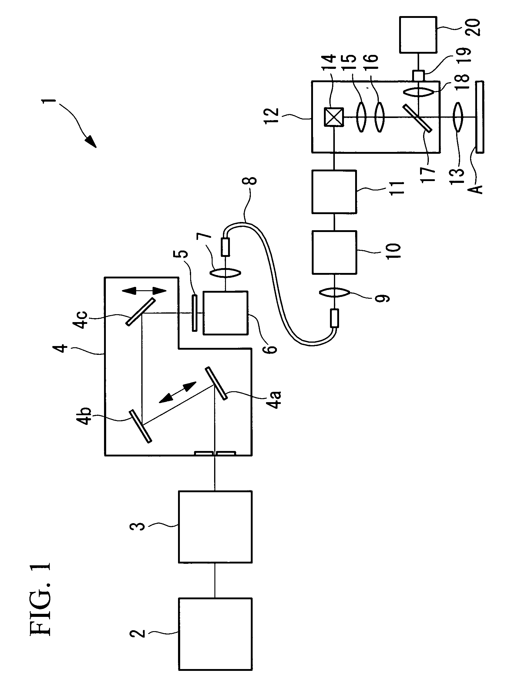
[0049]A laser microscope 1 according to an embodiment of the present invention is described below with reference to FIGS. 1 and 2.

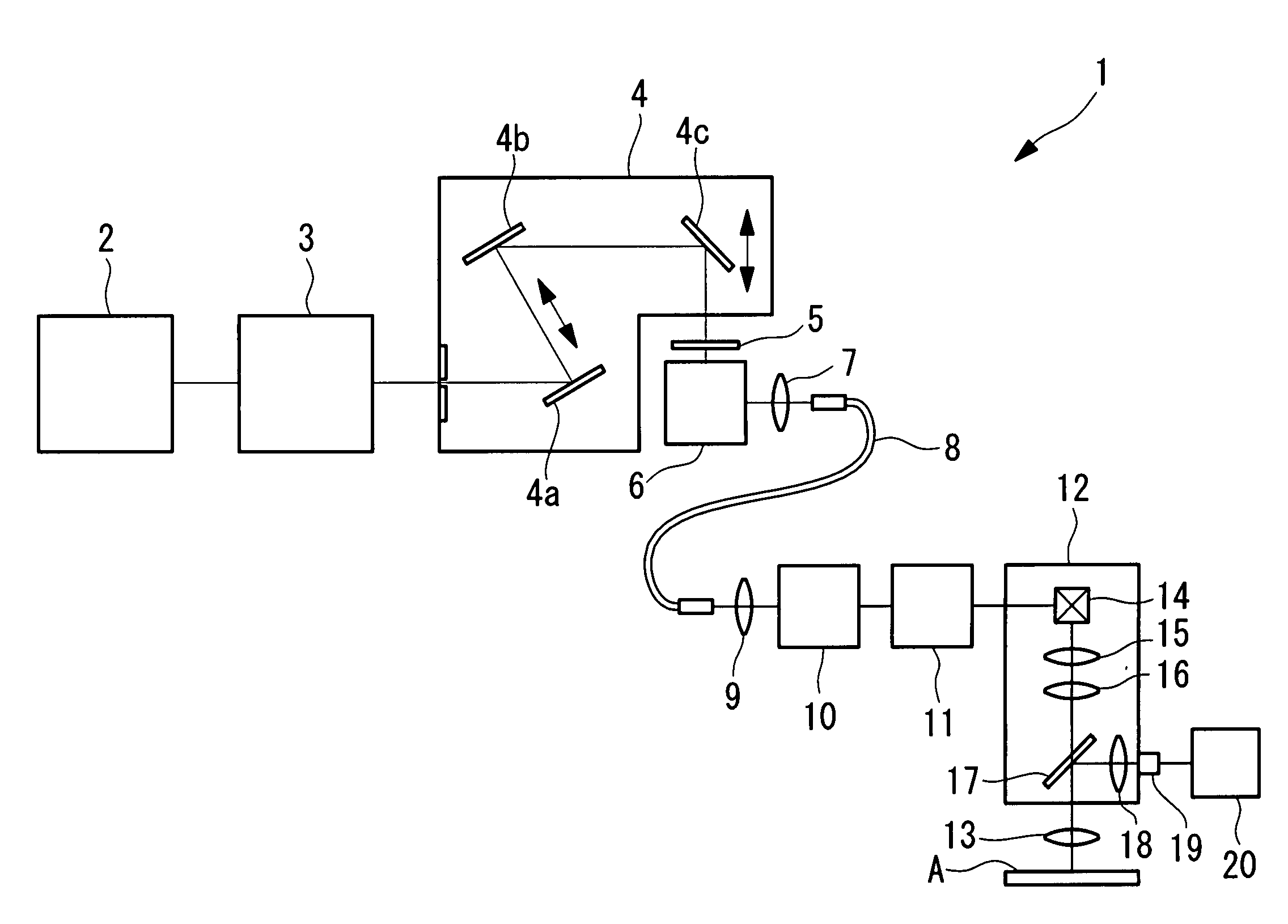
[0050]As shown in FIG. 1, the laser microscope 1 according to this embodiment is a multiphoton-excitation-type laser microscope in which a multiphoton-excitation effect is induced in a specimen A. The laser microscope 1 includes a laser light source 2 for emitting ultrashort-pulsed laser light, an average-output-power adjusting optical system 3, a pulse expander 4, a quarter-wave plate 5, an alignment-adjusting optical system 6, a coupling optical system 7, a large-diameter singe-mode fiber 8, a collimator optical system 9, a beam-shaping optical system 10, a pulse compressor 11, and a microscope main body 12, in this order from the laser light source 2 side.

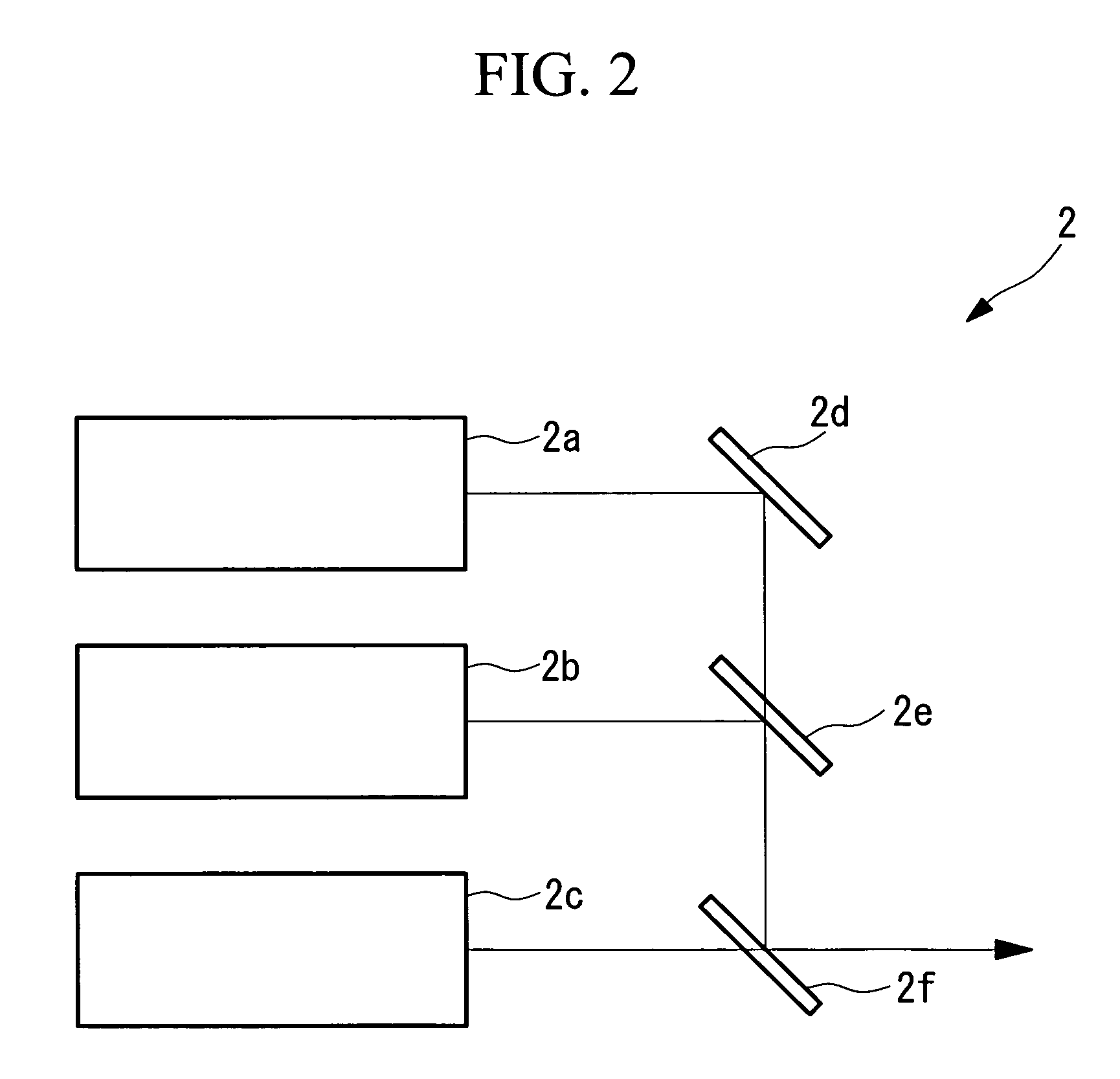
[0051]The laser light source 2 emits ultrashort-pulsed laser light with a tunable wavelength, for example, in the wavelength range of 700 to 1000 nm.

[0052]The average-output-power adjusting optical sy...


PUM


Abstract

It is possible to reduce a drop in output power in a positive-dispersion element used as a pulse compressor, thus improving multiphoton-excitation efficiency. Also, reducing the size of the positive-dispersion element makes it easier to attach it to a microscope main body and to accommodate it therein, thus improving maneuverability. The invention provides a laser microscope including a laser light source for emitting ultrashort-pulsed laser light; a pulse expander for expanding the ultrashort-pulsed laser light emitted from the laser light source; a large-diameter single-mode fiber for transmitting the ultrashort-pulsed laser light expanded by the pulse expander; a pulse compressor for compressing the ultrashort-pulsed laser light transmitted by the single-mode fiber; and a microscope main body for irradiating a specimen with the ultrashort-pulsed laser light compressed by the pulse compressor.

Description

BACKGROUND OF THE INVENTION[0001]1. Field of the Invention[0002]The present invention relates to laser microscopes.[0003]This application is based on Japanese Patent Application No. 2007-032247, the content of which is incorporated herein by reference.[0004]2. Description of Related Art[0005]Laser scanning microscopes of the multiphoton excitation type are known in the related art. These microscopes irradiate a specimen with ultrashort-pulsed laser light with an average output power of several milliwatts to several hundred milliwatts and a pulse width of several tens of femtoseconds to several hundred femtoseconds, via an objective lens, and observe multiphoton fluorescence produced by a multiphoton-excitation effect induced at the focal plane of the objective lens.[0006]In this type of laser-scanning microscope, it is preferable to introduce the laser light from the light source by using an optical fiber, which allows easy maneuverability and is highly convenient.[0007]When ultrash...

Claims


Application Information

Patent Timeline
Patent Type & Authority Applications(United States)
IPC IPC(8): G02B21/06
CPCG02F2203/26G02B21/0032
Inventor KUBO, HIROKAZU
Owner OLYMPUS CORP
Why Eureka
Try Eureka