Method For Forming Median Crack In Substrate And Apparatus For Forming Median Crack In Substrate

a technology of substrate and median crack, which is applied in the direction of manufacturing tools, instruments, non-linear optics, etc., can solve the problems of limited stress difference in forming cracks in the surface portion of brittle substrates, and achieve the effect of simplifying the mechanism, preventing thermal strain, and simplifying the control mechanism for the position of beam spots

Inactive Publication Date: 2008-08-14
MITSUBOSHI DIAMOND IND CO LTD
View PDF5 Cites 33 Cited by
  • Summary
  • Abstract
  • Description
  • Claims
  • Application Information

AI Technical Summary

Benefits of technology

[0038]In the case where the low temperature portions are regions directly beneath the non-irradiated portions which are not irradiated with a laser beam, the occurrence of thermal strain can be almost completely prevented in the low temperature portions. Accordingly, median cracks extending deep to the thickness-wise direction of the brittle substrate can be formed by supplying a small amount of thermal energy.
[0039]In the case where at least a portion of a substrate is irradiated with a laser beam a number of times where the low temperature portions correspond to portions that have been irradiated with a laser beam just once or a small number of times, high temperature portions and low temperature portions can be alternately formed without additionally using a masking member, or the like, thus simplifying the mechanism.
[0040]In the case where a masking member is placed on a brittle substrate so that a low temperature portion corresponds to a portion where a laser beam is blocked by the masking member, the control mechanism for the positions where beam spots are formed can be simplified.
[0041]In the case where a high absorption member, of which the ratio of absorption of a laser beam is higher than that of a brittle substrate, is provided on the brittle substrate so that a high temperature portion corresponds to a portion which is irradiated with a laser beam via the above described high absorption member, a necessary temperature gradient vis-a-vis a low temperature portion can be formed by supplying a small amount of thermal energy. Accordingly, stress that remains within the brittle substrate can be reduced, and thereby, median cracks extending deep to the thickness-wise direction of the brittle substrate can be formed.

Problems solved by technology

However, even when cooled spot 120 is formed, a sufficient difference in stress for forming a crack is limited in a surface portion of the brittle substrate.

Method used


Image

  • Method For Forming Median Crack In Substrate And Apparatus For Forming Median Crack In Substrate
  • Method For Forming Median Crack In Substrate And Apparatus For Forming Median Crack In Substrate
  • Method For Forming Median Crack In Substrate And Apparatus For Forming Median Crack In Substrate

Examples


embodiment 1

[0118]FIG. 8 shows the configuration of an apparatus 1 for forming a median crack that is utilized in each system of FIGS. 1, 2, 6 and 7.

[0119]In FIG. 8, the apparatus 1 for forming a median crack is provided with a laser tube 11, a beam transmission unit 12 for transmitting a laser beam that has been radiated from laser tube 11, a beam forming unit 13 for processing a laser beam that has been transmitted from the beam transmission unit 12 to a predetermined laser beam, a refrigerant supplying unit 14 for supplying a refrigerant onto a brittle substrate S, and a control unit 15 for controlling the respective units, laser tube 11, beam forming unit 13 and refrigerant supplying unit 14.

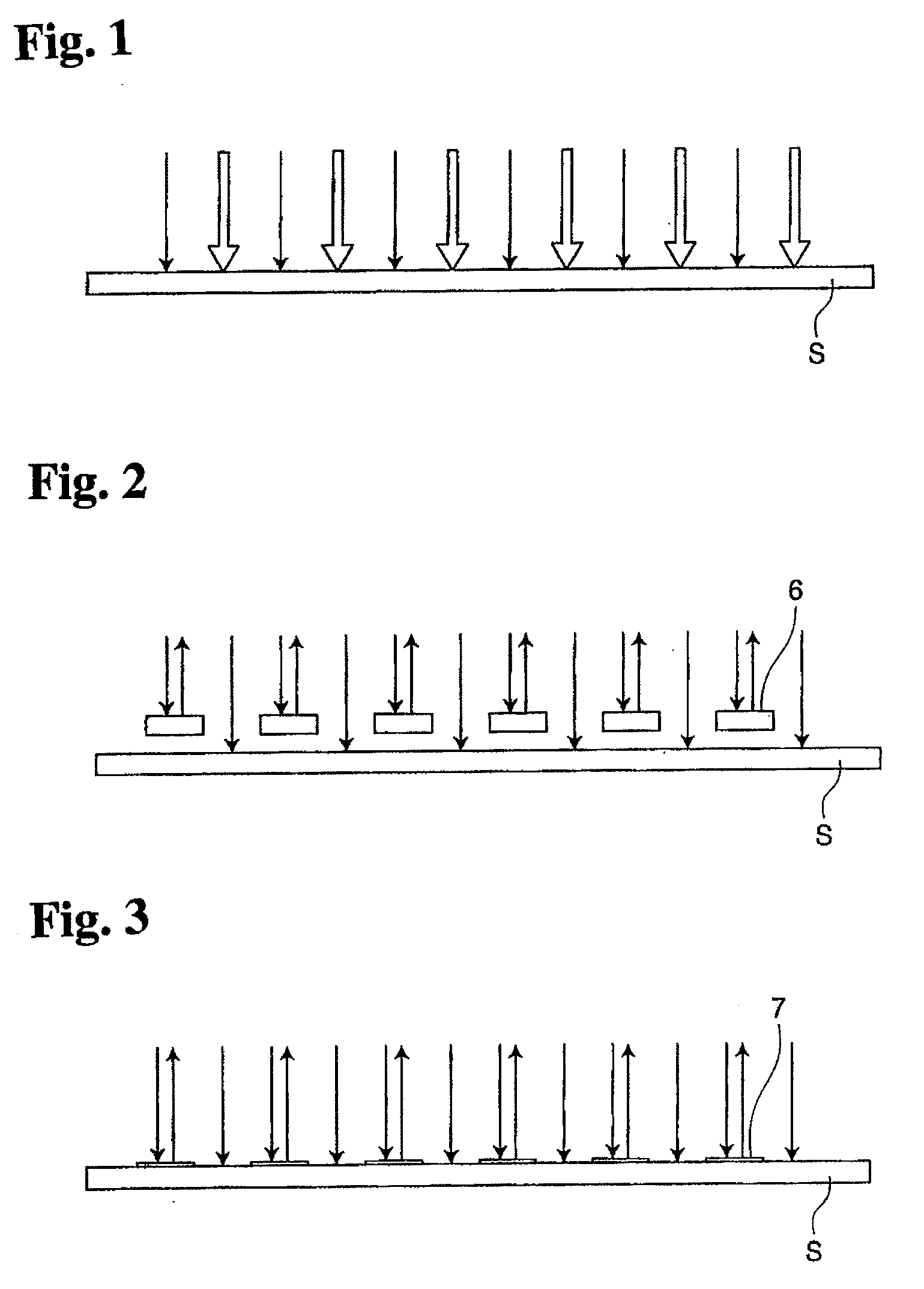
[0120]In the system of FIG. 1, where the configuration of FIG. 8 is utilized, control unit 15 commands beam forming unit 13 that is irradiated with a number of laser beams to alternately form high temperature portions and low temperature portions.

[0121]In the system of FIG. 2 for blocking laser beams, w...

embodiment 2

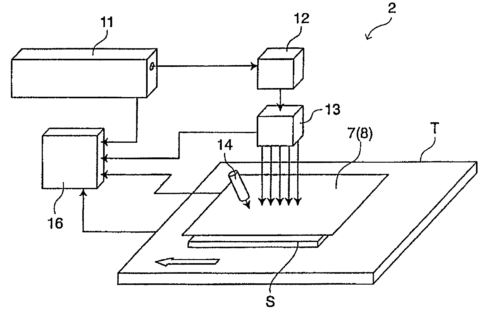
[0123]FIG. 9 shows the configuration of an apparatus 2 for forming a median crack that is utilized in the systems of FIGS. 3 and 4.

[0124]In FIG. 9, the apparatus 2 for forming a median crack is provided with a laser tube 11, a beam transmission unit 12 for transmitting a laser beam that has been radiated from laser tube 11, a beam forming unit 13 for processing a laser beam that has been transmitted from beam transmission unit 12 to a predetermined laser beam, a refrigerant supplying unit 14 for supplying a refrigerant, and a control unit 16 for controlling the respective units, laser tube 11, beam forming unit 13 and refrigerant supplying unit 14.

[0125]When a median crack is formed by apparatus for forming a median crack 2 of FIG. 9 in the system where the system of FIG. 3 is implemented so as to block a laser beam with which brittle substrate S is irradiated, a reflecting member 7 having a predetermined form, dimensions and slit intervals is placed along a laser-scribe line to be ...

embodiment 3

[0127]FIG. 10 shows the configuration of an apparatus 3 for forming a median crack that is utilized in the system of FIG. 5.

[0128]In FIG. 10, the apparatus 3 for forming a median crack is provided with a laser tube 11, a beam transmission unit 12 for transmitting a laser beam that has been radiated from laser tube 11, a beam forming unit 13 for processing a laser beam that has been transmitted from beam transmission unit 12 to a predetermined laser beam, a refrigerant supplying unit 14 for supplying a refrigerant, and a control unit 17 for controlling the respective units, laser tube 11, beam forming unit 13 and refrigerant supplying unit 14.

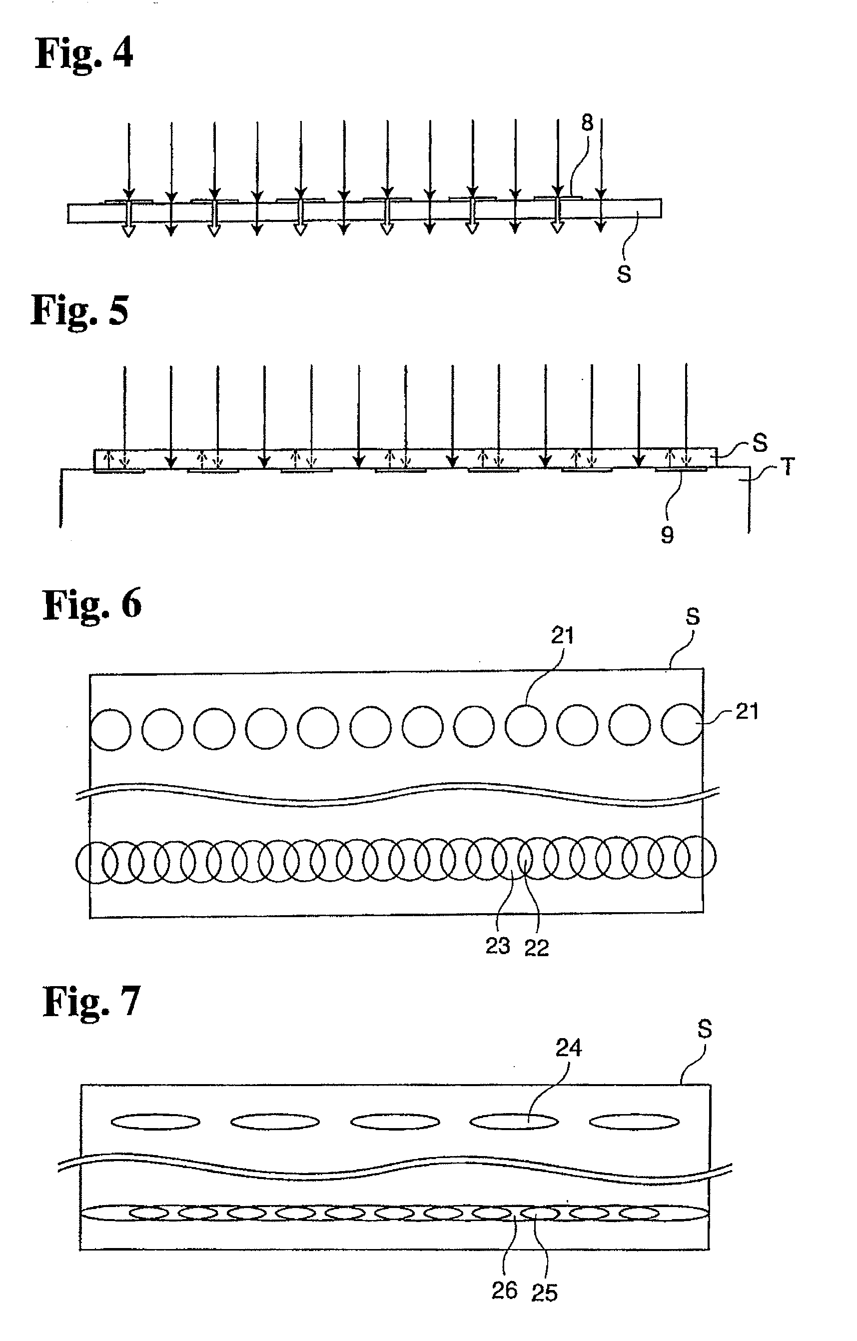
[0129]When a median crack is formed by apparatus for forming a median crack 3, first, a sheet of a reflecting member 9 is placed on the surface of a table on which a brittle substrate S is mounted. The sheet of reflecting member 9 is gained by forming reflecting member 9 having a predetermined form, dimensions and reflecting pattern intervals on...


PUM

PropertyMeasurementUnit
lengthaaaaaaaaaa
lengthaaaaaaaaaa
lengthaaaaaaaaaa

Abstract

A method for forming a median crack and an apparatus for forming a median crack are provided, where the formation of a deep, straight median crack is possible, and an excellent broken surface of a brittle substrate can be gained as a result of breaking.
In the method for forming a median crack in a brittle substrate, the brittle substrate is irradiated with a laser beam along a laser-scribe line to be formed with median cracks on the brittle substrate so as to be heated to a temperature that is no higher than its melting temperature, and thereby, a median crack is created along the laser-scribe line to be formed with median cracks and expanded starting from a notch that has been formed in the brittle substrate, and this method for forming a median crack in a brittle substrate is characterized in that high temperature portions that receive intense radiation from a laser beam, and low temperature portions that receive faint radiation from a laser beam are alternately formed along the laser-scribe line to be formed with median cracks.

Description

FIELD OF THE INVENTION[0001]The present invention relates to a method for forming a median crack in a substrate and an apparatus for forming a median crack in a substrate, and in particular, a method for forming a median crack in a substrate and an apparatus for forming a median crack in a substrate where a substrate is irradiated with a laser beam so as to be heated to a temperature that is no higher than its melting temperature along a laser-scribe line to be formed with median cracks on the substrate, and thereby, a median crack is formed starting from a notch that has been formed in advance.BACKGROUND OF THE INVENTION[0002]In order to laser-scribe a brittle substrate such as a semiconductor wafer and break it, a glass substrate or a ceramic substrate, a method for forming a median crack (or vertical crack) is used where a laser beam and a brittle substrate are relatively moved along a laser-scribe line to be formed with median cracks on the substrate so that the substrate is hea...

Claims


Application Information

Patent Timeline
Patent Type & Authority Applications(United States)
IPC IPC(8): H01L21/301B23K26/08B23K26/00B23K26/066B23K26/18B23K26/38B23K26/40B28D5/00C03B33/09G02F1/13G02F1/1333
CPCB23K26/4075C03B33/093B28D5/0011B28D1/221B23K26/40B23K2103/50B23K26/38B28D5/00
Inventor YAMAMOTO, KOJIHASAKA, NOBORU
Owner MITSUBOSHI DIAMOND IND CO LTD
Why Eureka
Try Eureka