
Maintenance Support System for Construction Machine

a construction machine and support system technology, applied in the field of maintenance support systems for construction machines, can solve the problems of anomaly of components produced sooner than the maintenance period of the standard maintenance schedule, hindering the user's work schedule, and increasing shipping costs

Inactive Publication Date: 2008-08-14
KOMATSU LTD
View PDF24 Cites 33 Cited by
  • Summary
  • Abstract
  • Description
  • Claims
  • Application Information

AI Technical Summary

Benefits of technology

[0008]An object of the present invention is to provide a maintenance support system for a construction machine that permits an improvement of the accuracy of a maintenance schedule for the construction machine.
[0009]A further object of the present invention is to provide a maintenance support system for a construction machine that allows a maintenance schedule for the construction machine to be accurately created by considering the actual operating condition of the construction machine.

Problems solved by technology

However, when the operating site of the construction machine is overseas, for example, if components are obtained after being judged to be abnormal, there is the possibility of the user's work schedule being hindered.
In addition, because airmail must be used for a timely supply of the component, there is the problem that shipping costs increase greatly.
Furthermore, when the driving and work and so forth of a construction machine are performed under more rigorous conditions than those first forecast, an anomaly of a component is produced sooner than the maintenance period of the standard maintenance schedule.
As a result, this means excessive costs for the manufacturer.

Method used


Image

  • Maintenance Support System for Construction Machine
  • Maintenance Support System for Construction Machine
  • Maintenance Support System for Construction Machine

Examples


first embodiment

[0057]Overall Constitution of System

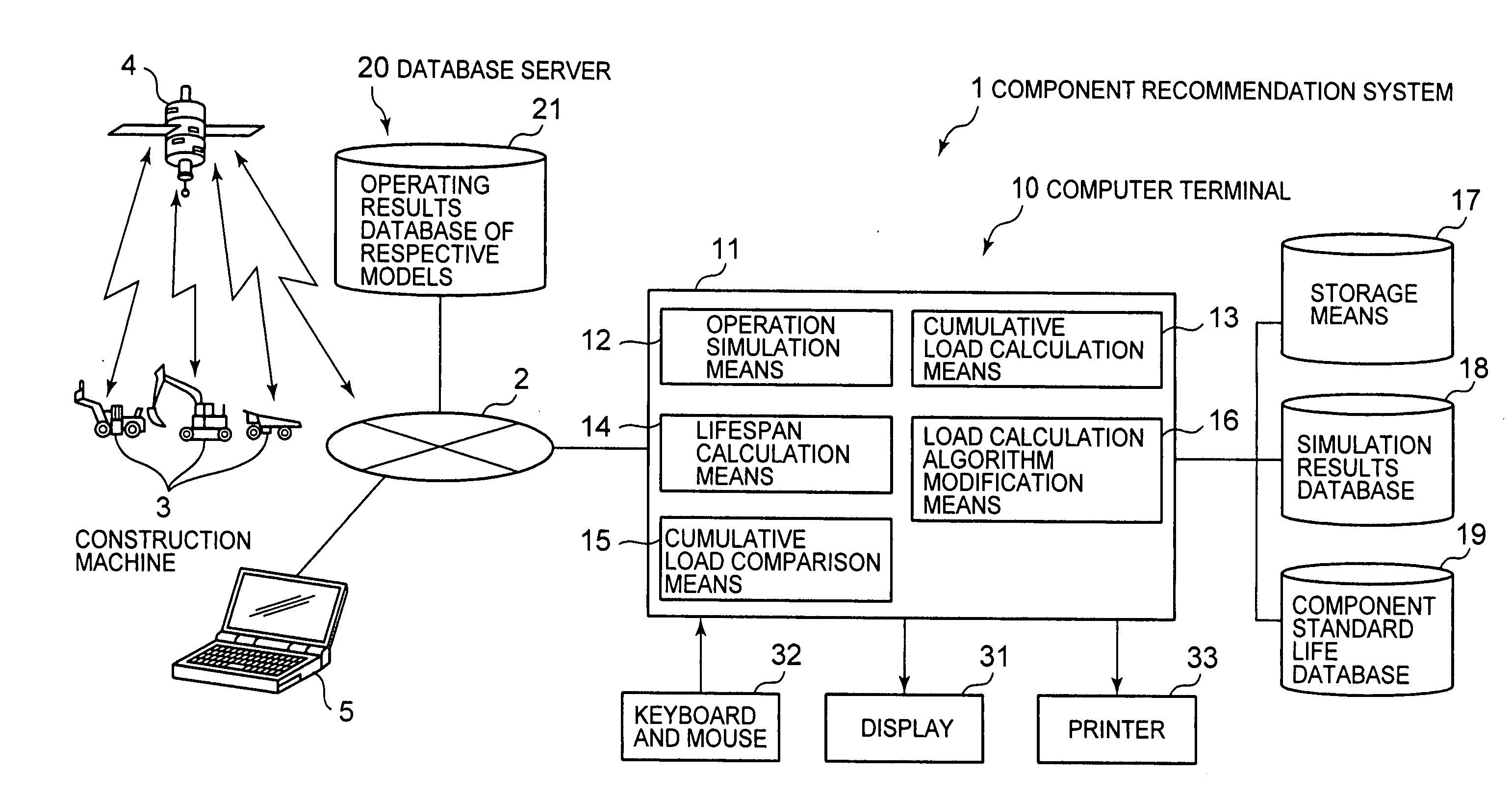
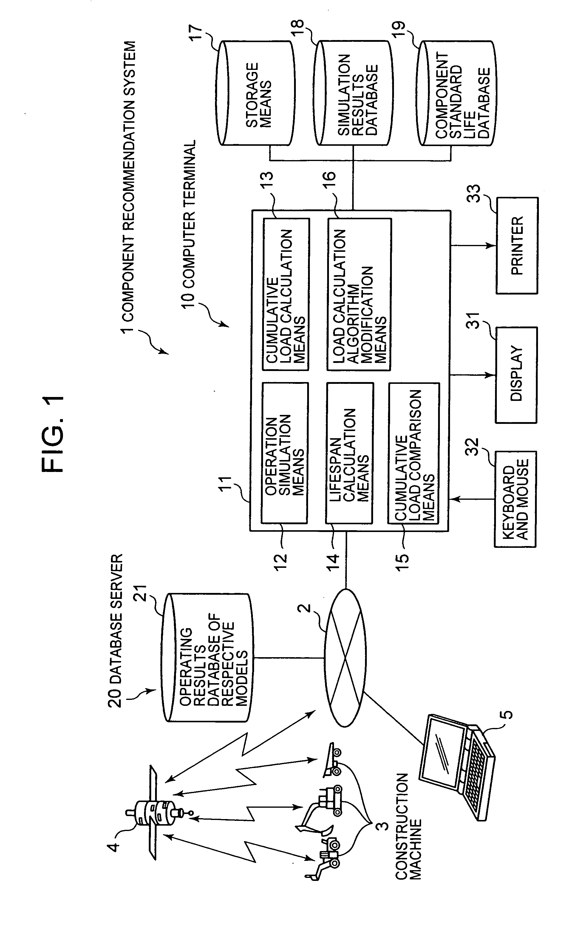
[0058]The component recommendation system 1 can be used to allow the construction machine manufacturer to make a variety of propositions to the customer who is a mine developer before mine development and so forth, for example. For example, the construction machine manufacturer is able to simulate and advocate a fleet configuration that satisfies the production operating conditions of the customer by using the system 1. A fleet configuration signifies a configuration of a construction machine group that is formed in order to achieve a certain objective. Further, the construction machine manufacturer is able to present the customer with information relating to a maintenance schedule for components required for a maintenance contract when a construction machine is purchased (servicing schedule, supply arrangement schedule and so forth) by using the system 1. In addition, the construction machine manufacturer is able to update the maintenance schedul...

second embodiment

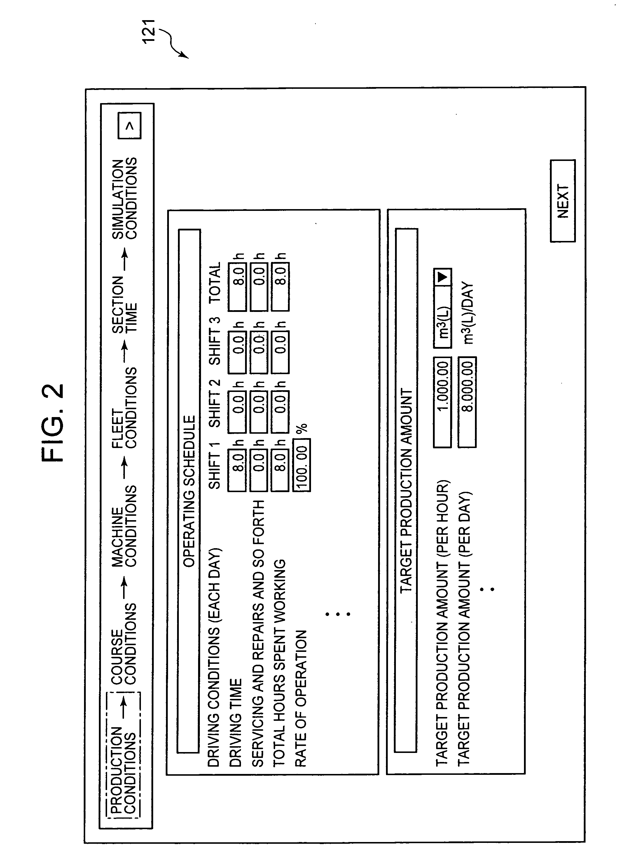
[0123]A more detailed, specific example of the above embodiment will be described hereinbelow. First, FIG. 19 shows a specific constitutional example of the operation simulation means 12. The operation simulation means 12 simulates the behavior of the respective construction machines 3 on the basis of the production operating conditions and the specifications of each of the construction machines 3 as mentioned earlier.

[0124]In the following example, a case where a plurality of dump trucks travel to and fro between a loading site and dump, for example, is described. That is, at the loading site, the loader loads earth and sand and ore and so forth into the dump truck. The dump truck in which the sand and earth and so forth are loaded moves to the dump via the course to dump the earth and sand at the dump. The dump truck with an empty load then returns via the course to the loading site and awaits the opportunity to load the sand and earth and so forth.

[0125]At the loading site, a wai...

third embodiment

[0170]FIG. 27 is a block diagram showing another constitutional example of the system of the present invention. In this example, the computer 10A is constituted as a server and a response is sent back in accordance with a request from another computer terminal 5.

[0171]The computer terminal 5 is a client terminal that is operated by the sales engineer of the construction machine manufacturer or sales agency or by a maintenance personnel or the like, for example. The terminal 5 can be connected to the server computer 10A via the communication network 2. The terminal 5 has a web browser 51 installed thereon, for example, and exchanges information with the server computer 10A via the web browser 51. For example, a mobile terminal such as a cellular phone, a Personal Digital Assistant (PDA), or handheld computer can be used as the client terminal 5.

[0172]Further, in this embodiment, a case where a large amount of maintenance support processing is processed by the server computer 10A is c...


PUM


Abstract

The present invention provides a maintenance support system for a construction machine that allows a components maintenance schedule to be accurately established.The system 1 calculates the cumulative load of every component corresponding with the driving and working conditions of the construction machine 3 by means of the load calculation means 13 after simulating the driving and working conditions on the basis of production operating conditions by means of the operation simulation means 12, and forecasts the lifespan of the respective components by means of the lifespan calculation means 14 on the basis of the cumulative load. Hence, a more accurate maintenance schedule can be established in comparison with a case where which component is to be maintained is determined on the basis of only the operating time as in the prior art. The possibility of an unexpected component anomaly occurring at an earlier stage than the predetermined lifespan can therefore be reduced.

Description

TECHNICAL FIELD[0001]The present invention relates to a maintenance support system for a construction machine.BACKGROUND ART[0002]In recent years, a system that acquires information relating to the operating time of construction machines by means of wireless communications and, when the cumulative operating time reaches a maintenance period decided by the maintenance schedule, prompts the user to maintain the component corresponding to the maintenance period has bee proposed (Japanese Patent Application Laid Open No. 2003-119831). That is, with this maintenance schedule, the decision on which component is to be maintained is made in accordance with the cumulative operating time of the construction machine.[0003]Further, according to Japanese Patent Application Laid Open No. 2003-119831 above, a multiplicity of sensor types that detect the operating states of the respective principal components are installed in a construction machine and, when it is judged that an anomaly has occurre...

Claims


Application Information

Patent Timeline
Patent Type & Authority Applications(United States)
IPC IPC(8): G06F15/00G06G7/70G06F17/10E02F9/20E02F9/26G01M99/00G06Q10/04G06Q50/00G06Q50/08G06Q50/10
CPCE02F9/26E02F9/20
Inventor OHKURA, YASUNORIMIWA, HIROBUMIKAWAKITA, MASAKAZUYOSHIMURA, TAKAHIRO
Owner KOMATSU LTD
Learn More